Quantcast
Channel: C++博客-eryar-随笔分类-2.OpenCASCADE
Viewing all 208 articles
Browse latest View live

OpenCASCADE JT Assistant

$
0
0

OpenCASCADE JT Assistant

eryar@163.com

Abstract. Siemens’ JT data format accepted as the world’s first ISO international standard for viewing and sharing lightweight 3D product information. OpenCASCADE JT Assistant is a viewer for files in JT format.

Key Words. Simens JT, JtOpen, OpenCASCADE, Jt Assistant

1. Introduction

西门子的JT(Siemens’s JT data format)文件格式是一个轻量级的数据交换格式,可用于在产品生命周期的各个阶段实时查看或共享产品的3D信息,并且已经通过ISO的认可作为了国际标准。通过将大量的CAD系统中的3D产品数据无缝衔接,JT加强了产品设计的协作,并且产品生命周期管理系统(Product Lifecycle Management, PLM)也支持这个标准。作为第一个轻量级的3D数据可视化世界ISO国际标准,JT将使制造厂商免去了对各种三维数据交换格式的依赖,并可轻松扩展3D可视化的应用,以便于使设计的协同性。

OpenCASCADE JT Assistant是一个JT格式数据可视化的小工具。由于JT格式在工业上的广泛应用,高性能、轻量级、灵活的用于三维产品可视化的文件格式。JT文件可包含工业规模的组件(多达100000部件)。有些船厂的PDM中就使用到了JT格式。JT Assistant处理JT网格支持延迟加载(late loading),还利用LOD(Level Of Detail)技术来提高显示性能。

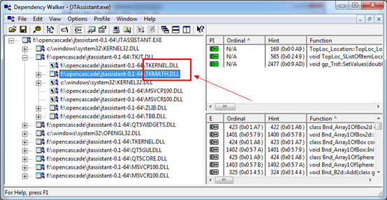
目前只提供了试用程序,将来OpenCASCADE准备提供开源版本的,仅支持GPL及商用License。Download binaries for Windows: ZIP archive (32 bits, 64 bits). 下载后用Dependency Walker打开查看引用关系如下图所示:

wps_clip_image-1578

Figure 1.1 JT Assistant in Dependency Walker

由上图可知,JT Assistant界面上用到了Qt5,关于OpenCASCADE的库只用到TKernel和TKMath。显示直接使用了OpenGL,没有用到Visualization中的库。

2.Supported JT data

目前JT Assistant支持JT 8.0-9.5,可显示网格及组装结构。整体式和非整体式的组件都是支持的。如果想测试一下程序,可从如下地址下载到一些JT文件:

v Siemens web site:

http://www.plm.automation.siemens.com/en_us/products/open/jtopen/technology/jt_showcase.shtml

v Grab CAD Site: http://grabcad.com/library/software/jt

wps_clip_image-32274

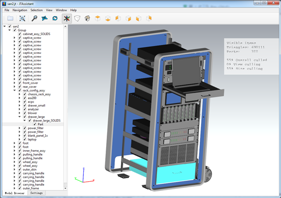
Figure 2.1 Navigation and Selection in the assembly structure

如上图所示,三维视图中的青色高亮部分与组装树上的Part是对应的,通过鼠标在三维视图中选择模型的同时,模型对应的组件树上部件也是同被选中。

wps_clip_image-25713

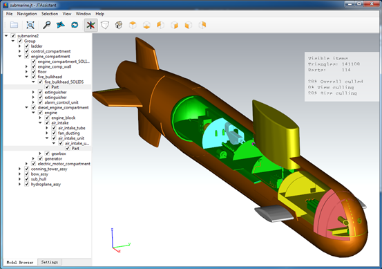
Figure 2.2 Submarine model 

wps_clip_image-11270

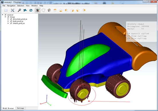
Figure 2.3 Wavecar model

从上图中可以发现,不知是这个JT文件有问题,还是JT Assistant程序有问题,显示得有点不正常。

wps_clip_image-30302

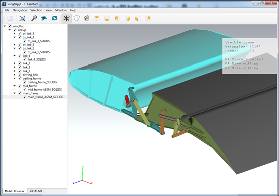
Figure 2.4 Wingflap model

wps_clip_image-16508

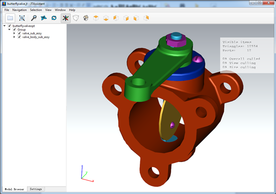
Figure 2.5 Bufferfly Valve model

wps_clip_image-350

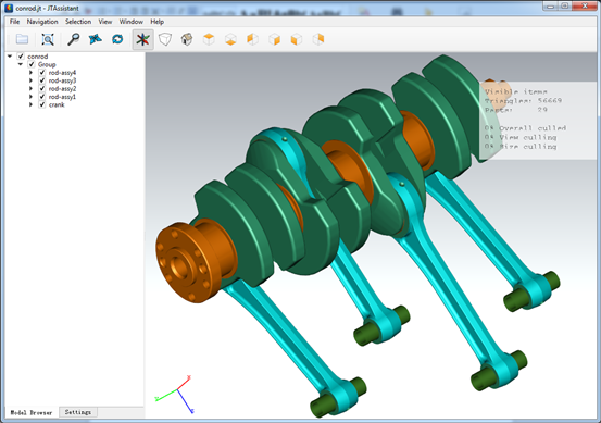
Figure 2.6 conrod Model

3.Conclusion

由上图可知,OpenCASCADE JT Assistant的显示效果还是很不错的,颜色、光照等调得很不错。用Qt来开发界面,还是比较方便,且效果也很不错。

有做工厂/船厂PDM系统的,如果涉及到三维产品数据的可视化,可以考虑采用JT这个轻量化的格式。

本文主要是翻译了OpenCASCADE网站上的内容,原文网址如下:

http://www.opencascade.org/support/applications/jt_assistant/

关于Jt格式的更多信息,可访问西门子的网站:

http://www.plm.automation.siemens.com/en_us/products/open/jtopen/index.shtml


eryar 2014-12-28 12:49 发表评论

A Simple OpenCASCADE Qt Demo-occQt

$
0
0

A Simple OpenCASCADE Qt Demo-occQt

eryar@163.com

Abstract. OpenCASCADE have provided the Qt samples in the samples directory, but they are a little complicated. So I decide write a simple OpenCASCADE Qt demo for the OpenCASCADE beginners. 

Key Words. OpenCASCADE6.8.0, Qt5.4

1. Introduction

OpenCASCADE is a software development platform providing services for 3D surface and solid modeling, CAD data exchange, and visualization. Most of OCCT functionality is avaiable in the form of C++ libraries. OCCT can be best applied in development of software dealing with 3D modeling(CAD), manufacturing/measuring(CAM) or numerical simulation(CAE). 

OpenCASCADE Technology is free software; you can redistribute it and or modify it under the terms of the GNU Lesser General Public License(LGPL) version 2.1, with additional exception. You can get the OpenCASCADE from here: http://www.opencascade.org/

wps_clip_image-20312

Figure 1.1 OpenCASCADE6.8.0 Release Notes

Qt is a cross-platform application framework that is widely used for developing application software with graphical user interface(GUI). Qt is free and open source software distributed under the terms of the GNU Lesser General Public License. 

Qt Services

Qt is a powerful framework that lets you create stunning user interfaces with amazing performance. We want to help you to achieve optimal results by using Qt building blocks in the best possible way, which is why we offer an extensive range of Qt advisory services. 

Code Less, Create More. Easily create connected devices, UIs and applications that run anywhere on any device. 

wps_clip_image-25919

Figure 1.2 Qt Ads

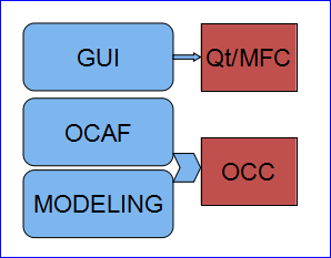
You can develop your program in the following manner:

wps_clip_image-19414

Figure 1.3 A application based on Qt and OpenCASCADE

You can use Qt for the GUI development, and for data management such as restore data from file or undo/redo support, you can choose OCAF, and for modeling algorithms, you can use OpenCASCADE. 

You can also use the Model/View/Controller of Qt to manage the data and undo/redo mechnism, to accelarate the developing.

OpenCASCADE have provided many samples to show its functions, but there are a lots codes, it is a little complicated for the beginner. I write a simple program to try OpenCASCADE in a straightforward way. I hope the demo can help you to understand the usage of OpenCASCADE.

The demo is based on OpenCASCADE6.8.0 and Qt5.4. Because of there are many bug fixes in OpenCASCADE new version6.8.0, especially the visualization module. So I update the code for the previous demo Qt with OpenCASCADE and add something new: 

http://www.cppblog.com/eryar/archive/2013/08/18/202617.aspx

2.View Operations

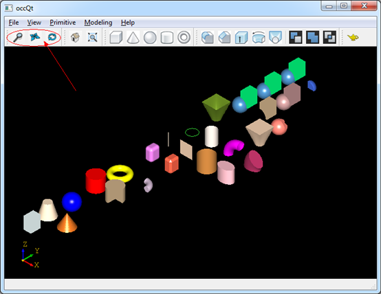
In occQt there are three operations to manipulate the view: pan, zoom and rotate, the following picture is the main window of occQt:

wps_clip_image-12250

Figure 2.1 occQt GUI

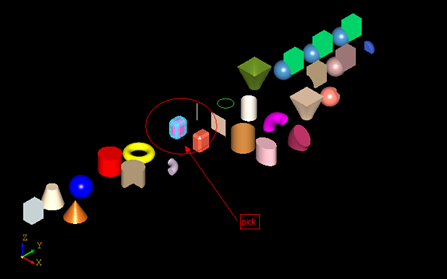
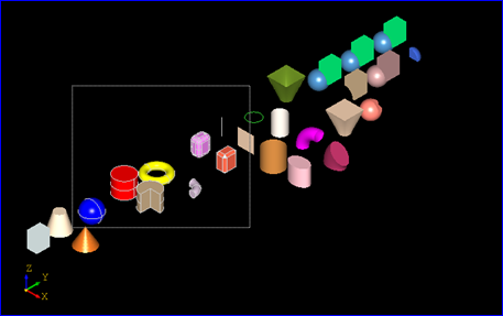
The options is for the middle button of the mouse, you can dragged the middle button of the mouse to pan, zoom and rotate the view. And the mouse left button is used for the pick and multi-select operation, single click you can pick a shape; drag left button will select all the shapes in the rectangle.

wps_clip_image-19038

Figure 2.2 Click mouse left button to pick

wps_clip_image-15699

Figure 2.3 Drag mouse left button to multi-select

The selected shapes will be hilighted, but now do not provide any operations for the selected shapes.

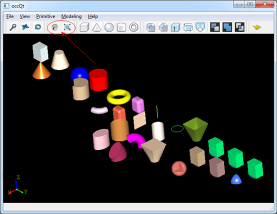
And also provide the Reset and Fit All function for the view:

wps_clip_image-6756

Figure 2.4 Reset and Fit all for the view

3.Make Primitives

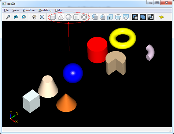
OpenCASCADE provides simple API for the construction of primitives, such as box, cone, sphere, cylinder, and torus, .etc. You can make a primitive by a simple class in OpenCASCADE, the sample code as follows:

TopoDS_Shape aTopoBox = BRepPrimAPI_MakeBox(3.04.05.0);
TopoDS_Shape aTopoCone 
= BRepPrimAPI_MakeCone(3.00.05.0);
TopoDS_Shape aTopoSphere 
= BRepPrimAPI_MakeSphere(3.0);
TopoDS_Shape aTopoCylinder 
= BRepPrimAPI_MakeCylinder(3.05.0);
TopoDS_Shape aTopoTorus 
= BRepPrimAPI_MakeTorus(3.01.0);

And the shapes in the viewer is in the following picture:

wps_clip_image-10519

Figure 3.1 Primitives in occQt

4.Modeling Algorithms

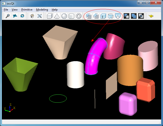
Modeling algorithms is the outstanding advantage of OpenCASCADE. But in occQt just give a example for the usage, you can check the documents and OpenCASCADE reference manual to have a look. The modeling algorithms in the occQt are:

v Fillet;

v Chamfer; 

v Extrude;

v Revol;

v loft.

wps_clip_image-29758

Figure 4.1 Modeling Algorithms in occQt

5.Boolean Operations

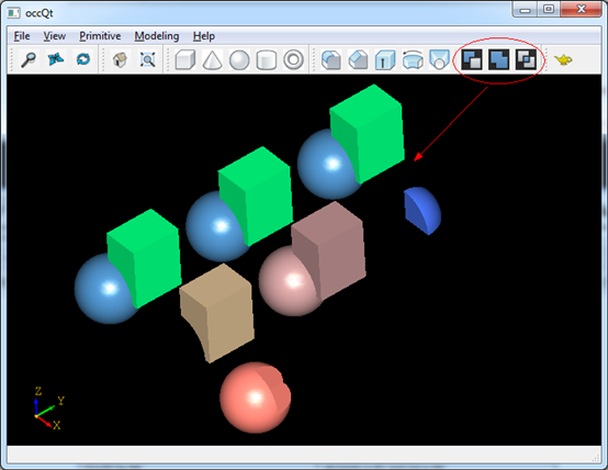
Boolean operations are used to create new shapes from the combinations of two shapes,

wps_clip_image-12858

The class to perform this is simple to use, they are:

TopoDS_Shape aFusedShape = BRepAlgoAPI_Fuse(S1, S2);
TopoDS_Shape aCommonShape 
= BRepAlgoAPI_Common(S1, S2);
TopoDS_Shape aCuttedShape 
= BRepAlgoAPI_Cut(S1, S2);

You can try this in occQt:

wps_clip_image-19041

Figure 5.1 Boolean operations in occQt

6. Conclusion

From the simple code demo, I hope it will help you to understand OpenCASCADE easily. Thanks for OpenCASCADE and Qt the amazing work. 

I put the code to GitHub: https://github.com/eryar/occQt/. You can download and have a try, then you can feedback or track the modification of occQt.

Enjoy!


eryar 2014-12-29 23:52 发表评论

OpenCASCADE Hidden Line Removal

$
0
0

OpenCASCADE Hidden Line Removal

eryar@163.com

Abstract. To provide the precision required in industrial design, drawings need to offer the possibility of removing lines, which are hidden in a given projection. OpenCASCADE provides two algorithms for this Hidden Line Removal component. The paper mainly translate the document of OpenCASCADE Modeling Algorithms, and give some applications in the plant design CAD software.

Key Words. OpenCASCADE, HLR, Hidden Line Removal

1. Introduction

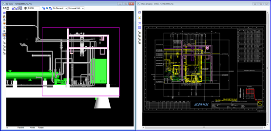
用计算机生成三维物体的真实图形是计算机图形学研究的重要内容,在用显示设备描述物体时,必须把三维的信息经过某种投影变换,在二维的显示平面上绘制出来。由于投影变换失去了深度信息,往往导致图形的二义性。要消除这类二义性,就必须在绘制时消除被遮挡的不可见的线或面,习惯上称之为消除隐藏线(Hidden Line Removal)或消除隐藏面(Hidden Face Removal)。在工程应用中,需要根据三维模型自动生成二维的图纸,用于指导生产。其中二维图纸中主要包括三维模型的消隐图、尺寸标注及件号标注等内容。如图1.1所示为某CAD软件中自动根据三维模型生成二维图纸的效果图:

wps_clip_image-698

Figure 1.1 Drawing generated from 3D model by PDMS

上图1.1所示为PDMS软件中自动生成的图纸,图纸中的图形区的管道模型就是根据三维模型自动投影及消隐后生成的。还生成尺寸标注及管道名称,以及右上角所件号标示或材料表等相关信息。

尽管现在3D PDF格式很流行,但是二维的生产图纸在目前国内的设计及施工单位中还是不可或缺的。当模型量大时,消隐速度快及自动生成的标注文字排列整齐(或满足工程习惯)成了二维图纸自动生成的核心技术,也是程序处理中的难点。

消隐算法的原理其实很简单,只要满足两个条件:

v 物体A在物体B的后面;

v 物体A与物体B在投影平面上有重叠部分;

前一个条件实际上是广义的,既可以是物体,也可以是面或线等。命题物体A在物体B后面成立,消隐计算就变成一个二维问题:物体A与物体B在投影平面上的重叠部分就是A被消除的部分。经过投影变换后,物体在投影平面上所占据的区域称为物体的落影区,物体上任何一点的投影均落在此落影区内。显然,若空间有两个物体的落影区是重叠的,则位于后面的物体将被前面的物体遮挡,被遮挡的部分就是落影区重叠的部分。消隐过程就是求取两者的公共部分,且由第三维深度坐标来判断两者的前后的过程。因为是线输出,这个过程就是一条条线与每一物体(面)的比较过程,最后可见部分的交集即为此线的最终可见部分。

OpenCASCADE提供了两种消隐算法:HLRBRep_Algo和HLRBRep_PolyAlgo。这些算法都是基于相同的原理:比较形状每条边相对每个面的可见性,并计算每条边的可见部分与消隐部分。算法通过计算在指定投影方向上的物体显示特性,去除或标记被面遮挡的边。这两个算法也与一些提取功能配合使用,如重构一个简化的模型等,简化后新的模型由边组成,就是在投影方向上的轮廓线。

HLRBRep_Algo是根据模型来计算的一种高精度的算法,而HLRBRep_PolyAlgo是基于离散数据的算法。当使用HLRBRep_Algo时可以得到精确结果,而使用HLRBRep_PolyAlgo可以提高计算速度。他们两个算法都可以处理任意类型的模型,如组合体、面或线,但也有些约束,如下情况就未被处理:

v 点未被处理;

v Z平面上没有被裁剪;

v 无限面或线没有处理;

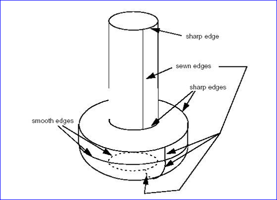
如图1.2所示为OpenCASCADE中的一些边的定义:

wps_clip_image-21746

Figure 1.2 Sharp, smooth and sewn edges in a simple screw shape

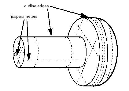
图1.3中的实线为同相形状的外轮廓线,虚线部分为等分参数线。

wps_clip_image-12863

Figure 1.3 Outline edges and isoparameters in the same shape

wps_clip_image-8933

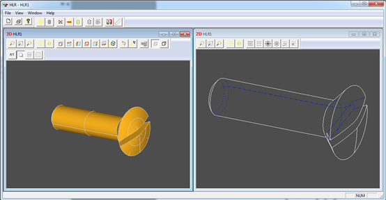
Figure 1.4 An extraction showing hidden sharp edges

如图1.4可以看出,蓝色虚线即为被遮挡的应该被去除的线。

2.HLR Usage

OpenCASCADE隐藏线去除算法的使用涉及以下几个步骤:

2.1 Loading Shapes

通过使用HLRBRep_Algo::Add()函数来将需要被消隐的形状加入到消隐算法中去。对于HLRBRep_PolyAlgo对象,使用HLRBRep_PolyAlgo::Load()函数来添加一个或多个需要处理的形状。

2.2 Setting View Parameters

通过函数HLRBRep_PolyAlgo::Projector()来设置投影方向,其参数为一个HLRAlgo_Projector对象。一般会根据三维视图数据来得到这个投影数据,进而来设置需要消隐的投影参数。

2.3 Computing the Projections

通过类HLRBRep_PolyAlgo中的函数HLRBRep_PolyAlgo::Update()来计算模型的外轮廓。当用类HLRBRep_Algo时,使用HLRBRep_Algo::Update()这个算法时,必须调用方法HLRBRep_Algo::Hide()来计算模型可见与隐藏线。使用类HLRBRep_PolyAlgo时,可见与隐藏线是通过HLRBRep_PolyHLRToShape来计算。

2.4 Extracting Edges

通过类HLRBRep_HLRToShape和HLRBRep_PolyHLRToShape来提取消隐后的模型数据,提取数据来源分别对应HLRBRep_Algo和HLRBRep_PolyAlgo对象。可提取的类型有:

v Visible/hidden sharp edges;

v Visible/hidden smooth edges;

v Visible/hidden sewn edges;

v Visible/hidden outline edges;

提取操作是由函数HLRBRep_PolyHLRToShape::Update来实现。

3.Examples

为了产生与AVEVA PDMS的Draft功能模块类似的功能,就需要隐藏线消除算法来自动根据模型生成二维图纸。如下代码为测试HLR算法的一个简单示例:

osg::Node* TestPolyHlr(void)
{
    osg::ref_ptr
<osg::Geode> aGeode = new osg::Geode();
    osg::ref_ptr
<osg::Geometry> aLineGeometry = new osg::Geometry();
    osg::ref_ptr
<osg::Vec3Array> aVertices = new osg::Vec3Array();

    TopoDS_Shape aPipeModel;
    BRepTools::Read(aPipeModel, 
"d:/PipeModels/2007.brep", BRep_Builder());

    BRepMesh_IncrementalMesh aMesher(aPipeModel, 
0.1);

    OSD_Timer aTimer;
    aTimer.Start();

    Handle_HLRBRep_PolyAlgo aHlrPolyAlgo 
= new HLRBRep_PolyAlgo();

    HLRAlgo_Projector aProjector;
    HLRBRep_PolyHLRToShape aHlr2Shape;

    aHlrPolyAlgo
->Load(aPipeModel);

    aHlrPolyAlgo
->Projector(aProjector);
    aHlrPolyAlgo
->Update();

    aHlr2Shape.Update(aHlrPolyAlgo);

    aTimer.Stop();
    aTimer.Show(std::cout);

    
for (TopExp_Explorer e(aHlr2Shape.VCompound(), TopAbs_EDGE); e.More(); e.Next())
    {
        TopoDS_Edge anEdge 
= TopoDS::Edge(e.Current());
        TopoDS_Vertex aFirstVertex 
= TopExp::FirstVertex(anEdge);
        TopoDS_Vertex aLastVertex 
= TopExp::LastVertex(anEdge);
        gp_Pnt aFirstPoint 
= BRep_Tool::Pnt(aFirstVertex);
        gp_Pnt aLastPoint 
= BRep_Tool::Pnt(aLastVertex);

        aVertices
->push_back(osg::Vec3(aFirstPoint.X(), aFirstPoint.Y(), aFirstPoint.Z()));
        aVertices
->push_back(osg::Vec3(aLastPoint.X(), aLastPoint.Y(), aLastPoint.Z()));
    }

    
for (TopExp_Explorer e(aHlr2Shape.OutLineVCompound(), TopAbs_EDGE); e.More(); e.Next())
    {
        TopoDS_Edge anEdge 
= TopoDS::Edge(e.Current());
        TopoDS_Vertex aFirstVertex 
= TopExp::FirstVertex(anEdge);
        TopoDS_Vertex aLastVertex 
= TopExp::LastVertex(anEdge);
        gp_Pnt aFirstPoint 
= BRep_Tool::Pnt(aFirstVertex);
        gp_Pnt aLastPoint 
= BRep_Tool::Pnt(aLastVertex);

        aVertices
->push_back(osg::Vec3(aFirstPoint.X(), aFirstPoint.Y(), aFirstPoint.Z()));
        aVertices
->push_back(osg::Vec3(aLastPoint.X(), aLastPoint.Y(), aLastPoint.Z()));
    }

    aLineGeometry
->setVertexArray(aVertices);
    aLineGeometry
->addPrimitiveSet(new osg::DrawArrays(osg::PrimitiveSet::LINES, 0, aVertices->size()));

    aGeode
->addDrawable(aLineGeometry);

    
return aGeode.release();
}

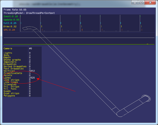
根据上述用法介绍一步一步来,就可以生成只包含线段数据的消隐后的结果,然后再在OpenSceneGraph中显示结果如下图所示:

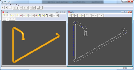
wps_clip_image-27133

Figure 3.1 HLR for pipe model

wps_clip_image-29066

Figure 3.2 HLR pipe model in OpenSceneGraph

wps_clip_image-3222

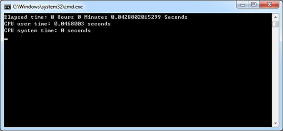
Figure 3.3 HLR time usage

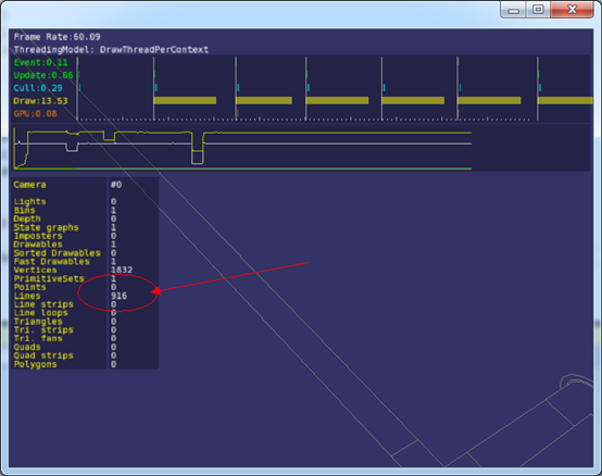
由图3.2可知,一个简单的管道模型经过HLRBRep_PolyAlgo消隐后,产生很多线段数据,但是由图3.3可知,HLR消隐速度还是比较快的。因为HLRBRep_PolyAlgo是基于离散网格及可视化数据的,所以当离散精度降低时,会产生较少数据。如下图为降低离散精度后,产生的线段数据明显减少。

wps_clip_image-3530

Figure 3.4 HLR pipe model in less tesslate precision

wps_clip_image-7385

Figure 3.5 HLR pipe model in less tesslate precision time usage

由图3.4和图3.5可知,当降低模型的离散精度时,在不影响消隐后二维图形质量的情况下,消隐后产生的线段数据明显减少,且消隐算法的速度也明显要快很多。所以离散精度也是HLR消隐算法的一个关键因素,使用消隐HLR算法时需要选择合适的离散精度。

4.Conclusion

综上可知,OpenCASCADE的隐藏线消除HLR算法使用起来还是比较简单的,不过彻底理解算法,还是需要静下心来,Debug进代码,在理解大概原理的基础上,对其实现作进一步的理解。

要使用OpenCASCADE的HLR算法,只要指定好投影参数及加载好待消隐的模型,即可得到消隐后的模型的二维数据了。若想加快算法速度事减少模型的二维轮廓数据,则需要选择合适的网格离散精度。

5. References

1. OpenCASCADE Modeling Algorithms User Guide6.8.0 2014

2. 何援军. 计算机图形学. 机械工业出版社. 2010

3. 孙家广. 计算机图形学. 清华大学出版社. 2000


eryar 2015-01-05 18:39 发表评论

Qt Undo Framework Demo

$
0
0

Qt Undo Framework Demo

eryar@163.com

Abstract. Qt’s Undo Framework is an implementation of the Command Pattern, for implementing undo/redo functionality in applications. The Command pattern is based on the idea that all editing in an application is done by creating instances of command objects. Command objects apply changes to the document and are stored on a command stack. Furthermore, each command knows how to undo its changes to bring the document back to its previous state. As long as the application only uses command objects to change the state of the document, it is possible to undo a sequence of commands by traversing the stack downwards and calling undo on each command in turn. It is also possible to redo a sequence of commands by traversing the stack upwards and calling redo on each command. 

Key Words. Qt, Undo/Redo, Command Pattern, Model/View

1. Introduction

在交互应用程序中撤销和重做(Undo/Redo)能力是很重要的。像常见的软件Office,AutoCAD等,有了撤销功能,用户体验更舒服。一般都会使用Command模式来实现这一功能。

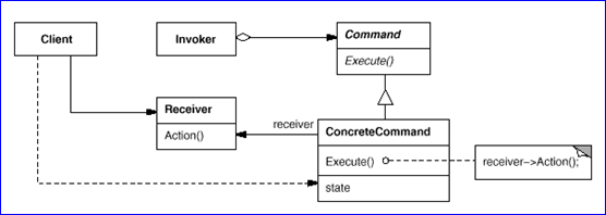
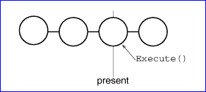
命令模式通过将请求本身变成一个对象来使工具箱对象可向未指定的应用对象提出请求,这个对象可被存储并像其他对象一样被传递。这一模式的关键是一个抽象的Command类,它定义了一个可执行操作的接口。其最简单的形式是一个抽象的Execute操作。具体的Command子类将接收者作为其一个实例变量,并实现Execute操作,指定接收者采取动作,而接收者执行该请求所需要的具体信息。在GoF的《Design Patterns》中,给出了Command模式的一般结构,如图1.1所示:

wps_clip_image-581

Figure 1.1 Command pattern structure

将一个请求封装为一个对象,从而使你可用不同的请求对客户进行参数化;对请求排队或记录成日志,以及支持可撤销的操作。

支持任意层次的撤销和重做命令的最后一步是定义一个命令历史记录(Command History),或称为已执行的命令列表。从概念上理解,命令的历史记录看起来有如下形状:

wps_clip_image-5187

Figure 1.2 Command History

每个圆代表一个Command对象,标有present的对象即为当前命令对象。当我们调用Unexecute()后,标有present的对象将会向左移;当调用Execute(),标有present的对象将会向右移。重复这个过程,我们可以进行多层次的撤销,层次数只受命令历史记录长度的限制。

在Qt的Undo框架中主要包括以下几个类:

v QUndoCommand:这个类相当于Command模式中的那个抽象基类Command,所有这些命令都被保存到undo栈中,在其派生类中实现undo和redo函数。

v QUndoStack:这个相当于命令历史记录,其中保存了Command对象的列表。

v QUndoGroup:是一个undo stack的组合。

v QUndoView:是显示undo堆栈中内容的一个列表组件,在这个视图中点击命令的名称也可以实现与Undo/Redo按钮相同的作用。

本文通过一个简单的例子来示例Qt中Undo框架,先在简单的List模型中实现,进而在Tree上实现。掌握Qt的这个框架,就可以不用OpenCASCADE的OCAF了,并且Qt的代码用起来还是相对简单清晰的。

2.Example

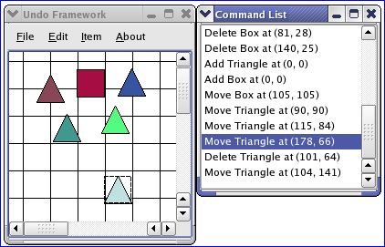
Qt提供了一个Undo框架的示例,程序还涉及到图形绘制相关的内容,程序效果如下图2.1所示:

wps_clip_image-17325

Figure 2.1 Qt Undo Framework Example

结合这个示例程序,学习一下Qt的Undo框架,从而写出一个更简单的程序,代码如下所示:

class InsertCommand : public QUndoCommand
{
public:
    InsertCommand(
const QModelIndex& theIndex, QStringListModel* theModel);
    
~InsertCommand();

public:
    
virtual void undo();
    
virtual void redo();

private:
    QModelIndex mIndex;
    QStringListModel
* mModel;
};

首先,从QUndoCommand派生出一个插件字符串的类InsertCommand,并要实现undo()和redo()这两个虚函数,实现代码如下所示:

void InsertCommand::undo()
{
    mModel
->removeRows(mIndex.row(), 1);
}

void InsertCommand::redo()
{
    mModel
->insertRows(mIndex.row(), 1);
    mModel
->setData(mIndex, QString("Insert string " + QString::number(mIndex.row())));
}

这样在响应工具栏按钮的函数中,只需要生成这个命令,并将命令加入到命令栈中即可,代码如下:

void undoTest::insertString()

{
    QModelIndex aIndex 
= mListView->currentIndex();

    mUndoStack
->push(new InsertCommand(aIndex, mListModel));
}

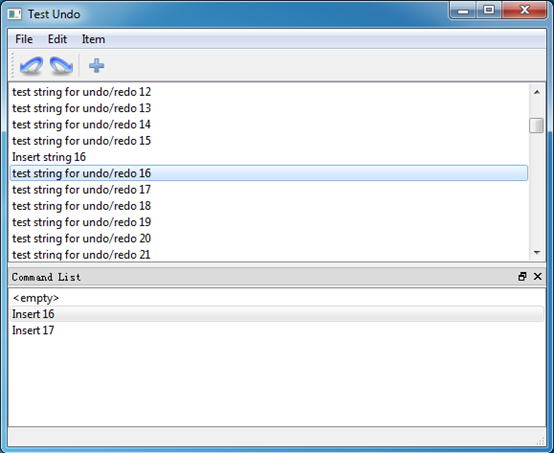
程序运行效果如下图2.2所示:

wps_clip_image-9457

Figure 2.3 Test Qt Undo Framework

通过工具栏上的undo/redo及命令列表中选择,都可以实现命令的回退及重做。完整的程序代码可通过文后链接下载。

3.Conclusion

在学习C++基本语法后,可以看看GoF的《设计模式》。刚刚接触可能感觉有些抽象,这时可以使用Qt来编写一些程序来练练手。用Qt来编程感觉比MFC要舒服很多,有些类封装得很直接,易于使用。尽管MFC中也有个Document/View的设计模式,但是Qt中的MVC用起来更直接。通过使用现有的框架,来理解那些抽象的设计模式,从而加深面向对象的观念,让自己的程序更简单,有趣。

OpenCASCADE的OCAF框架也提供了一个数据框架,基于这个树形的框架,可以存储层次表示的数据,且也提供了Undo/Redo的支持。基于OCAF框架,可以快速开发出一定功能的专业软件了。但是要使用OCAF框架,涉及的OpenCASCADE库很多。如果打算开发一个轻量级的三维程序,而又正好选择了Qt来开发GUI,这时就可以考虑使用Qt的MVC框架及在这个框架上的Undo/Redo功能,这样开发效率可以相对高一些,且程序发布时依赖的动态库也要少很多。

流行的工厂设计软件中的数据框架多用树形结构,树中每个结点上的属性可以让用户自由扩展,像OCAF中通过TDataStd_Integer添加一些整数属性一样,及用TDataStd_Name添加名称属性。但是OCAF中添加属性有些局限性,因为每种属性是用GUID来区别的,所以每个结点上同一种属性只能有一个。

所以用Qt的MVC框架来根据需要实现一个自定义的树形Model,再基于V3d_Viewer实现一个显示三维的View,即可以实现一个简单,但看上去相对专业的CAD建模程序了。

4. References

1. GoF. Design Patterns-Elements of Reusable Object-Oriented Software.机械工业出版社. 2010

2. Qt5.4. Overview of Qt’s Undo Framework. 2014

3. Qt5.4. Undo Framework Example. 2014

4. OpenCASCADE6.8.0. OCAF. 2014

5. OpenCASCADE6.8.0. OCAF White Paper. 2014

6. OpenCASCADE6.8.0. Distribution of Data Through OCAF Tree. 2014


PDF Version and Source code: Qt Undo Framework Demo


eryar 2015-01-13 18:59 发表评论

Iterate Files by Tcltk

$
0
0

Iterate Files by Tcltk

eryar@163.com

Abstract. Tcl/Tk provide a programming system for developing and using graphical user interface(GUI) applications. Tcl stands for “tool command language” and is pronounced “tickle”, is a simple scripting language for controlling the extending applications. The blog use Tcl/Tk to iterate all the files for a given directory, this is useful to some automation work, such as change all the file names for a given directory; add copyright info for the source code files.
Key Words. Tcl/Tk, Iterate Files,遍历文件夹中所有文件

1. Introduction

Tcl/Tk是一种用于易于使用的脚本语言,可以用来对程序进行扩展及完成一些自动化的工作,加上内置的一些命令,其功能要比Windows中的DOS的批处理命令功能更强大,使用更方便。Tcl脚本语言是开源免费的,可以方便获取且免费使用。

OpenCASCADE中使用了Tcl/Tk来实现了一个自动化测试体系。使用在OpenCASCADE中使用自定义的Tcl命令,可以快速来检验算法的结果。通过编写脚本文件,实现了测试的自动化。所以学习一下Tcl/Tk脚本语言,并在实际的工作中加以应用,可以将一些机械的劳动交给计算机自动完成。

本文主要说明如何使用Tcl/Tk来遍历指定文件夹中所有文件。利用此功能,可以稍微加以扩展,就可以完成一些实际的重复劳动。如遍历指定目录中所有的源文件或指定类型的文件,添加上版权信息等。

2. Tcl/Tk Code

要遍历指定目录下所有的文件,包括子文件夹,需要用到命令glob及一个递归函数。脚本代码如下所示:

#
# Tcl/Tk script to iterate all the files for a given directory.
# eryar@163.com
# 2015-01-18
#


package require Tcl
package require Tk

wm title 
. "Iterate Files"

label 
.labelDirectory -text "Directory "
entry 
.entryDirectory -width 30 -relief sunken -textvariable aDirectory
button 
.buttonDirectory -text "" -command {chooseDirectory .entryDirectory}

button 
.buttonApply -text "Apply" -command {perform $aDirectory}
button 
.buttonCancel -text "Cancel" -command {exit}

grid 
.labelDirectory .entryDirectory .buttonDirectory
grid 
.buttonApply .buttonCancel

# chooseDirectory--
# choose the directory to iterate.

proc chooseDirectory {theEntry} {
    set dir [tk_chooseDirectory 
-initialdir [pwd] -mustexist 1]
    
    
if {[string compare $dir ""]} {
        
$theEntry delete 0 end
        
$theEntry insert 0 $dir
        
$theEntry xview end
    }
}

# perform--
# perform the algorithm.
#

proc perform {theDirectory} {
    puts 
"Iterate all the files in $theDirectory"
    
    
if {[string length $theDirectory< 1} {
        tk_messageBox 
-type ok -icon warning -message "Please select the directory!" -parent .
        
return 
    }
    
    
# process the iterate
    process $theDirectory
}

# process--
# recursion every folder and file.
#

proc process {theFolder} {

    set aFiles [
glob -nocomplain -directory $theFolder *]
    
    
foreach aFile $aFiles {
        
if {[file isfile $aFile]} {
            
# just output the file name here. 
            # you can do something such as rename for the file.

            puts "$aFile \n"
        } 
else {
            process 
$aFile
        }
    }
}

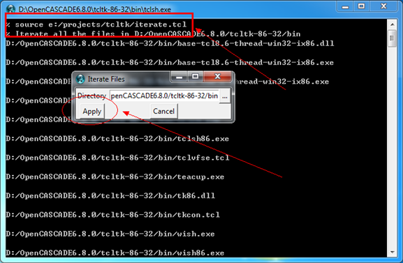
程序用法为打开Tcl解释器,使用命令source加载脚本文件,如下图所示:

wps_clip_image-20196

Figure 2.1 Tcl usage

3. Conclusion

通过应用Tcl/Tk来体验脚本编程的乐趣,并加深对Tcl/Tk的理解。从而对OpenCASCADE的模块Draw Test Harness更好地理解。

如果有编程基础,Tcl/Tk会很快入门的。入门后,可以应用其直接编写一些有意思有脚本,来实现一些重复工作的自动化。也可将Tcl加入到自己的程序中,增加程序的二次开发功能。

可见,玩一玩脚本语言,还是非常有趣的!


PDF Version and Script: Iterate Files by Tcl


eryar 2015-01-18 12:08 发表评论

OpenCASCADE General Transformation

$
0
0

OpenCASCADE General Transformation

eryar@163.com

Abstract. OpenCASCADE provides a general transformation class: gp_GTrsf. It can be a transformation from gp, an affinity, or you can define your own transformation giving the matrix of transformation. The general transformation contains the vectorial part of the transformation and the translation part. A GTrsf transformation is only applicable to coordinates. Be careful if you apply such a transformation to all points of a geometric object, as this can change the nature of the object and thus render it incoherent. Typically a circle is transformed into an ellipse by an affinity transformation. To avoid modifying the nature of an object, use a gp_Trsf transformation instead, as objects of this class respect the nature of geometric objects.

Key Words. OpenCASCADE, Transformation, Affinity Transformation

1. Introduction

仿射变换(Affinity Transformation)是指线性变换后接着平移。因此,仿射变换的集合是线性变换的超集,任何线性变换都是仿射变换,但不是所有的仿射变换都是线性变换。

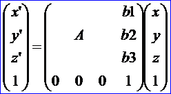
仿射变换的定义如下:在空间直角坐标系下,点(x,y,z)与点(x’, y’,z’)之间的变换

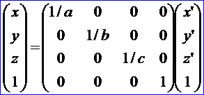
wps_clip_image-2056

称为仿射变换。如果采用特殊的齐次坐标来表达,仿射变换也可用下列形式:

wps_clip_image-15105

空间仿射变换是把平面变换到平面,直线变换到直线。两个平行平面的像也是平行的。共线三点的的简单比是不变量。平行六面体的体积是权为1的相对不变量。

OpenCASCADE的TKMath库中提供了这上仿射变换类gp_GTrsf,它能执行比gp_Trsf更通用的变换。对于TopoDS_Shape,OpenCASCADE分别提供了如下两个类进行变换:

v BRepBuilderAPI_GTransform

v BRepBuilderAPI_Transform

本文在OpenCASCADE Draw Test Harness中给出这两个类实现变换的结果。如果不想改变几何的特性,只想改变模型的位置或朝向,建议采用BRepBuilderAPI_Transform。

2.BRepBuilderAPI_Transform

OpenCASCADE中使用算法BRepBuilderAPI_Transform来实现:平移、旋转、缩放及镜像变换。在Draw Test Harness中实现的函数代码如下所示:

static Standard_Integer transform(Draw_Interpretor& di,Standard_Integer n,const char** a)
{
  
if (n <= 1return 1;

  gp_Trsf T;
  Standard_Integer last 
= n;
  
const char* aName = a[0];

  Standard_Boolean isBasic 
= Standard_False;

  
if (!strcmp(aName,"reset")) {
  }
  
else {
    isBasic 
= (aName[0== 'b');
    aName
++;

    
if (!strcmp(aName,"move")) {
      
if (n < 3return 1;
      TopoDS_Shape SL 
= DBRep::Get(a[n-1]);
      
if (SL.IsNull()) return 0;
      T 
= SL.Location().Transformation();
      last 
= n-1;
    }
    
else if (!strcmp(aName,"translate")) {
      
if (n < 5return 1;
      T.SetTranslation(gp_Vec(Draw::Atof(a[n
-3]),Draw::Atof(a[n-2]),Draw::Atof(a[n-1])));
      last 
= n-3;
    }
    
else if (!strcmp(aName,"rotate")) {
      
if (n < 9return 1;
      T.SetRotation(gp_Ax1(gp_Pnt(Draw::Atof(a[n
-7]),Draw::Atof(a[n-6]),Draw::Atof(a[n-5])),
                    gp_Vec(Draw::Atof(a[n
-4]),Draw::Atof(a[n-3]),Draw::Atof(a[n-2]))),
                    Draw::Atof(a[n
-1])* (M_PI / 180.0));
      last 
= n-7;
    }
    
else if (!strcmp(aName,"mirror")) {
      
if (n < 8return 1;
      T.SetMirror(gp_Ax2(gp_Pnt(Draw::Atof(a[n
-6]),Draw::Atof(a[n-5]),Draw::Atof(a[n-4])),
                  gp_Vec(Draw::Atof(a[n
-3]),Draw::Atof(a[n-2]),Draw::Atof(a[n-1]))));
      last 
= n-6;
    }
    
else if (!strcmp(aName,"scale")) {
      
if (n < 6return 1;
      T.SetScale(gp_Pnt(Draw::Atof(a[n
-4]),Draw::Atof(a[n-3]),Draw::Atof(a[n-2])),Draw::Atof(a[n-1]));
      last 
= n-4;
    }
  }

  
if (T.Form() == gp_Identity || isBasic) {
    TopLoc_Location L(T);
    
for (Standard_Integer i = 1; i < last; i++) {
      TopoDS_Shape S 
= DBRep::Get(a[i]);
      
if (S.IsNull())
        di 
<< a[i] << " is not a valid shape\n";
      
else
        DBRep::Set(a[i],S.Located(L));
    }
  }
  
else {
    BRepBuilderAPI_Transform trf(T);
    
for (Standard_Integer i = 1; i < last; i++) {
      TopoDS_Shape S 
= DBRep::Get(a[i]);
      
if (S.IsNull()) {
        di 
<< a[i] << " is not a valid shape\n";
      }
      
else {
        trf.Perform(S);
        
if (!trf.IsDone())
          
return 1;
        DBRep::Set(a[i],trf.Shape());
      }
    }
  }
  
return 0;
}

下面给出应用Tcl脚本来实现这些变换的例子:

# make rotated copies of a sphere in between two cylinders
# create a file source toto.tcl
# toto.tcl code:

pload ALL

#create a sphere
psphere s 3
ttranslate s 
25 0 12.

for {set i 0} {$i < 360} {incr i 20} {
    copy s s
$i
    trotate s
$i 0 0 0 0 0 1 $i
    
    vdisplay s
$i
}
# create two cylinders
pcylinder c1 30 5
copy c1 c2
ttranslate c2 
0 0 20
vdisplay c1 c2 s

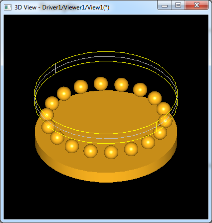
脚本运行效果如下图所示:

wps_clip_image-18963

Figure 2.1 Transform Tcl demo

从Draw中实现的函数来看,移动、旋转及缩放变换都是使用类

BRepBuilderAPI_Transformation来实现。Tcl脚本中先创建出一个球体,再平移后,复制13份,最后又创建出两个圆柱体。如果要对TopoDS_Shape进行变换且不改变其中的几何性质,建议都使用这个类来完成。

3.BRepBuilderAPI_GTransform

在OpenCASCADE也可使用仿射变换BRepBuilderAPI_GTransform来对形状实现上述变换操作,还可提供变形的变换,因此仿射变换是更一般的变换方法。在Draw中实现的函数代码如下所示:

///=======================================================================
// gtransform
//=======================================================================
static Standard_Integer deform(Draw_Interpretor& di,Standard_Integer n,const char** a)
{
  
if (n <= 1return 1;
  
  Standard_Integer last 
= n;
  
  gp_Trsf T;
  gp_GTrsf GT(T);
  
//  gp_Mat rot(Draw::Atof(a[last-3]),0,0,0,Draw::Atof(a[last-2]),0,0,0,Draw::Atof(a[last-1]));
  gp_Mat rot(Draw::Atof(a[3]),0,0,0,Draw::Atof(a[4]),0,0,0,Draw::Atof(a[5]));
  GT.SetVectorialPart(rot);
  last 
-= 3;
  BRepBuilderAPI_GTransform gtrf(GT);
  BRepBuilderAPI_NurbsConvert nbscv;
  
//  for (Standard_Integer i = 1; i < last; i++) {
  
//    TopoDS_Shape S = DBRep::Get(a[i]);
  TopoDS_Shape S = DBRep::Get(a[2]);    
  
if (S.IsNull()) {
    
//cout << a[2] << " is not a valid shape" << endl;
    di << a[2<< " is not a valid shape" << "\n";
  }
  
else {
    gtrf.Perform(S);
    
if (gtrf.IsDone()){
      DBRep::Set(a[
1],gtrf.Shape());
    }
    
else {
      
return 1;
    }
  }
  
  
return 0;
}

根据仿射变换的定义,给定一个球面的数学表达式:

wps_clip_image-14741

应用如下的仿射变换,将会得到一个椭球面:

wps_clip_image-5848

由变换公式解得:

wps_clip_image-13797

将它代入球面方程得到:

wps_clip_image-17839

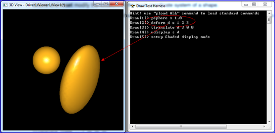
在Draw中使用BRepBuilderAPI_GTransform变换得到如下图所示:

wps_clip_image-23346

Figure 3.1 Shape Deformation

关于仿射变换有个重要定理:一般仿射变换是正交变换、沿着三个互相正交方向的压缩或放大和平移这三者的乘积。上述命令的实现代码就是设置了仿射矩阵中的a,b和c值,从而达到对模型变形的效果。

4.Conclusion

在三维建模软件中经常需要对模型的位置和其朝向进行变换,如果不想改变模型中的几何特性,在OpenCASCADE中建议使用类BRepBuilderAPI_Transform来实现。如果需要对模型进行更通用的变换即仿射变换,可以使用类BRepBuilderAPI_GTransform来实现。使用此类后,会改变模型中的几何特性,必须谨慎使用。

5. References

1. OpenCASCADE, OpenCASCADE Draw Test Harness User Guide, 2014

2. 苏步表, 华宣积. 应用几何教程. 复旦大学出版社. 2012

3. Fletcher Dunn. 3D Math Primer for Graphics and Game Development. Wordware. 2002


eryar 2015-01-22 20:30 发表评论

Undo/Redo for Qt Tree Model

$
0
0

Undo/Redo for Qt Tree Model

eryar@163.com

Abstract. Qt contains a set of item view classes that use a model/view architecture to manage the relationship between data and the way it is presented to the user. The separation of functionality introduced by this architecture gives developers greater flexibility to customize the presentation of items, and provides a standard model interface to allow a wide range of data sources to be used with existing item views. Model 3D aided design software such as AVEVA Plant/PDMS, Marine use the architecture to manage the design data source. The article demonstrate the Undo/Redo on the Qt Tree model.

Key Words. Model/View, MVC pattern, Undo/Redo, Tree Model

1. Introduction

现代稍微大型一点的软件,要处理的数据量通常会比较大。这时就需要有一个唯一的数据源,且会对这个数据源中的数据进行增、删、改的操作。如果没有统一的数据源,数据会随意地被创建和删除,且创建和删除的用户界面也不统一,不利于软件管理。基于唯一的数据源,并在这个基础上提供统一的增删改接口,不仅有利于软件数据管理,还有利于事务的处理,即Undo/Redo功能。若引入脚本语言,如Tcl或Python,甚至可实现脚本命令对数据的操作,为程序增加二次开发功能。

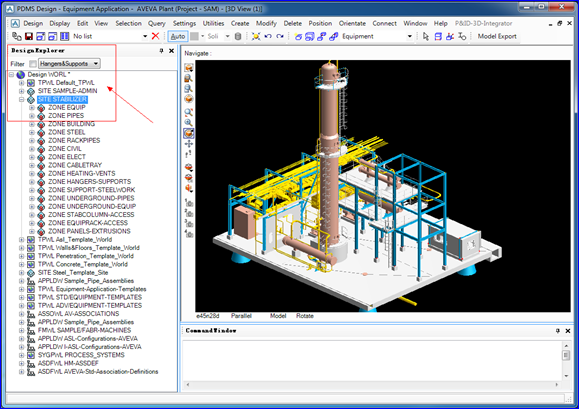
wps_clip_image-28934

Figure 1. AVEVA Plant/PDMS Software

如上图1所示为英国剑桥大学CADCENTRE出品的AVEVA Plant/PDMS软件。PDMS使用了统一的数据源,左边的导航树及右边的三维模型都是这个数据源的一种展示方式,可以在导航树上创建及删除数据;也可以在三维视图中进行交互,方便地创建及修改模型。这种方式与GoF描述的Observer观察者模式相似,即:

定义对象间的一种一对多的依赖关系,当一个对象的状态发生改变时,所有依赖于它的对象都得到通知并被自动更新。

对应上面的软件,即对于唯一的数据源这个对象,导航树及三维视图都依赖于他。当数据源这个对象中有数据的增删改时,导航树及三维视图都会得到通知并自动更新了。

图1右下角的CommandWindow中可以输入命令,即PML,也可以对数据源进行修改。引入Observer模式,即可实现这些功能。

Qt中包含了一系列的Model/View类,这些类都是基于MVC架构的,这种将数据与视图分开的处理,使同一个数据源可以不同的视图中进行展示,且不需要修改数据源的结构。Qt中基于Command命令模式实现了一个Undo/Redo的框架,将Undo/Redo框架应用于Model/View的类,即可得到与AVEVA Plant/PDMS中类似的功能。

本文主要对Qt中的model/view及undo/redo框架进行介绍,及如何将Undo/Redo框架应用到model/view中去,实现对以层次方式组织数据的树模型进行undo/redo,进而实现一个三维CAD工厂设计的原型。

2.Tree Model

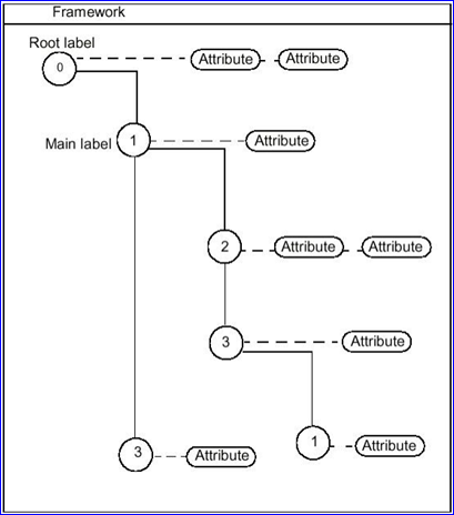
软件中使用层次方式来组织数据,可护展性好。如OpenCASCADE中的OCAF框架的数据也是树形方式组织:

wps_clip_image-28088

Figure 2.1 OpenCASCADE OCAF data tree

每个Label中可以存放属性,还包含子Label,这样就提供了一个通用的程序框架,灵活使用,可以用一种统一的方式来存放数据。有一个缺点就是每个Label中的属性类型只能包含一种,这种方式相对于AVEVA的自定义属性UDA来说,就显得很不方便了,需要提前对数据的存储进行规划,扩展起来稍有不便。

AVEVA中对每个数据Element都提供了自定义属性(User Definable Attribute),每种类型的属性(数值型、字符串型等)都可以包含任意数量,没有限制。所以可扩展性更好。

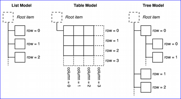
Qt中基于MVC模式的model/view架构提供了一些预定义的模型及视图,如列表模型及对应的视图,树模型及树视图等。在model/view架构中,为model提供了统一的访问数据的方式,即Model Index。对于列表model,通过QModelIndex::row()即可访问。对于表格model,需要QModelIndex::row()和QModelIndex::column()。对于树model,除了上述两个函数,还需要提供QModelIndex::parent()来对父节点进行访问。如下图2.2所示:

wps_clip_image-11793

Figure 2.2 Schematic view of Qt’s Models

若需要对列表及表格model应用Undo框架,还是很方便的,只要记住数据操作的对应的row或row及column即可。若要对树形model进行undo,原理也是一样的,即在redo中生成数据在undo中恢复数据。

3.Key Points

将undo框架与model/view结合有两种方式:

v 通过在undo/redo命令中调用QAbstractItemModel的API来改变底层数据;

v 自定义model使其创建命令并推送到undo栈Stack中去;

第一种方式看起来要容易些,且可与任意model结合。The first approach seems simpler, as it works with any model and gives the undo framework total control --- you can create as many different types of commands as you want and each of them can call a number of methods from the model API in their undo() and redo() routines.

当model中有delete操作时,会将index内部的数据删除。对于这种情况,需要注意。Qt给出了两个解决办法:

There are two things to remember. The first is that, if you delete items, rows or columns, you should save the data of all the items getting deleted(including children) somewhere so that you can later revert the deletion. The second is that it would be nice to be able to set meaningful descriptions of commands pushed on the stack. To do that you can provide methods in the model, that are called each time a command is pushed onto the stack, which should each return a description based on the parameters of the command being executed.

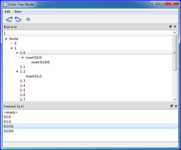
基于上述思想,实现了Tree Model与Undo Framework结合的一个小例子:

wps_clip_image-2472

Figure 3. Undo/Redo and Tree Model

4.Conclusion

Qt中基于Command命令模式的Undo框架,需要对数据操作及恢复仔细考量。尤其对于有删除数据的操作,若以QModelIndex作为参考依据,则会出错。对于此Qt提供了两个解决思路。

基于Qt的model/view及undo框架,也可以方便实现OpenCASCADE中的OCAF框架许多类似的功能,且Qt的代码可读性更高。若要快速开发程序,可以考虑使用Qt的model/view框架。

感谢晓天的建议。

5. References

1. Using Undo/Redo with Item Views. http://doc.qt.digia.com/qq/qq25-undo.html

2. OpenCASCADE. OCAF User’s Guide. 2014

3. GoF. Design Patterns-Element of Reusable Object-Oriented Software. 1995


eryar 2015-01-28 20:57 发表评论

Create views of OpenCASCADE objects in the Debugger

$
0
0

Create views of OpenCASCADE objects in the Debugger

eryar@163.com

Abstract. The Visual Studio Natvis framework lets you customize the way Visual Studio displays native types in debugger variable windows such as the Watch, Locals and Data Tips windows. It supersedes the autoexp.dat file that has been used in earlier versions of Visual Studio and offers XML syntax, better diagnostics, versioning, and multiple file support. The container in OpenCASCADE is difficult for debugging, such as TColStd_Array1OfInteger in the TColStd package, .etc. Use the natvis framework to create views of these objects will make it easy for developers to inspect them during debugging and so accelerate the debug process.

Key Words. Visual Studio Natvis, OpenCASCADE

1. Introduction

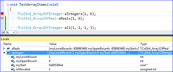
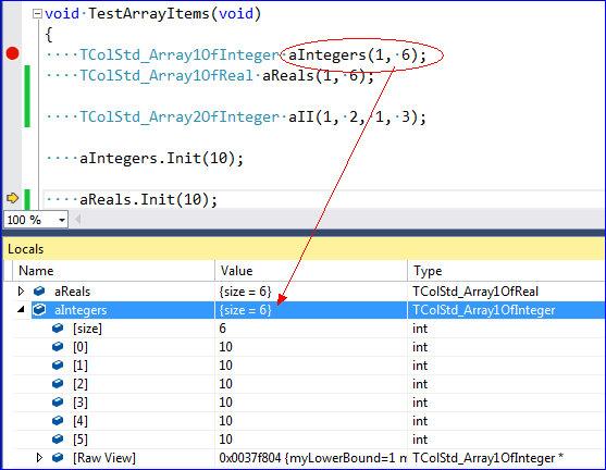
因为OpenCASCADE早期使用C开发,所以自定义了一些容器类,如包TColStd中的类,TColGeom包及包TopTools中的类等,这些类在C++中都可以使用STL来替代了。这些类在Debug过程中,很难查看其中的值,如TColStd_Array1OfInteger,这个类相当于std::vector<int>,但是Debug时只能看到数据的指针,不容易查看容器中每个元素的值,如下图1.1所示:

wps_clip_image-3641

Figure 1.1 View of TColStd_Array1OfInteger in Locals Window

由上图1.1可知,对于这个类的对象,Debug时只能看到数据的起始指针。为了方便自定义类型调试,Visual Studio在2012版本以后,引入了Natvis框架,用来替代原来的autoexp.dat来为自定义类型定义调试时的数据显示。Natvis使用了XML文件,可读性更好,易于实现。

本文使用Visual Studio的Natvis框架,来对OpenCASCADE中的一些容器类数据进行可视化,方便开发者对OpenCASCADE的调试。

2.For Array Container

对于OpenCASCADE的包TColStd中的数组类,定义其natvis如下所示:

<Type Name="TColStd_Array1OfInteger">
    
<DisplayString Condition="isAllocated != 1">empty</DisplayString> 
    
<DisplayString>{{size = {myUpperBound - myLowerBound + 1}}}</DisplayString>
    
<Expand>
        
<Item Condition="isAllocated == 1" Name="[size]">myUpperBound - myLowerBound + 1</Item>
        
<ArrayItems Condition="isAllocated == 1">
            
<Size>myUpperBound - myLowerBound + 1</Size>
            
<ValuePointer>(Standard_Integer*)(myStart) + myLowerBound</ValuePointer>
        
</ArrayItems>
    
</Expand>
</Type>

调试时数据显示如下图2.1所示:

wps_clip_image-9252

Figure 2.1 OpenCASCADE array in Locals Windows

同理,可对此包中其他一维数组使用同样的规则,即可对其中的数据可视化,与std::vector显示的效果一样,方便调试。

3.For List Container

对于OpenCASCADE的包TColStd中的链表类,定义其natvis如下所示:

<Type Name="TColStd_ListNodeOfListOfInteger">
    
<DisplayString>{{current = {myValue}}}</DisplayString>
    
<Expand>
        
<LinkedListItems>
            
<HeadPointer>this</HeadPointer>
            
<NextPointer>(TColStd_ListNodeOfListOfInteger*)myNext</NextPointer>
            
<ValueNode>this-&gt;myValue</ValueNode>
        
</LinkedListItems>
    
</Expand>
</Type>

<Type Name="TColStd_ListOfInteger">
    
<DisplayString Condition="myFirst == 0">empty</DisplayString>
    
<Expand>
        
<Item Name="first">(TColStd_ListNodeOfListOfInteger*)myFirst</Item>
    
</Expand>
</Type>

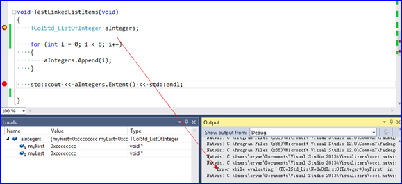
调试时对于类TColStd_ListOfInteger,natvis诊断说找不到类TColStd_ListNodeOfListOfInteger定义,当跟踪到此类一个具体函数时,就可以看到具体的值了:

wps_clip_image-12159

Figure 3.1 Natvis gives a Error info

跟踪到TColStd_ListOfInteger内部后,就可以看到类TColStd_ListNodeOfListOfInteger中的数据了,但是从TColStd_ListOfInteger的函数中出来后,就看不到了。

如果这个问题解决了,对于类TopoDS_ListOfShape中的数据也可以用同样的方式来显示,极大地方便了开发者对其调试。如果你对此有解决办法,欢迎不吝赐教。

wps_clip_image-11017

Figure 3.2 Data view for TColStd_ListNodeOfListOfInteger

先从简单的容器类着手,解决后可将TopoDS_ListOfShape中的数据显示出来,为OpenCASCADE程序的调试提供方便。

4.Conclusion

Visual Studio 2012版本以后引入了Natvis框架来对自定义的类进行可视化,方便调试。OpenCASCADE中有很多容器类直接使用了指针,调试程序时数据很不直观。应用Natvis来对一些类在调试时的视图进行配置,可以方便查看其中数据,使OpenCASCADE的调试更轻松。

对于一维数组的natvis定义还是很简单的,但是对于List出现了问题。如果这个问题解决了,对TopoDS_ListOfShape的可视化也可做同样的处理,方便造型算法调试。若您有解决方案,望不吝赐教。

5. References

1. Create custom views of native objects in the debugger. 

https://msdn.microsoft.com/en-us/library/vstudio/jj620914.aspx

2. Writing debugger type visualizers for C++ using .natvis files

https://code.msdn.microsoft.com/Writing-type-visualizers-2eae77a2#content

3. vczh. C++实用技巧之配置Visual C++的调试器显示数据结构的格式.

http://www.cppblog.com/vczh/archive/2013/03/21/198665.html

4. stl.natvis in %VSINSTALLDIR%\Common7\Packages\Debugger\Visualizers

5. qt5.natvis in %VSINSTALLDIR%\Common7\Packages\Debugger\Visualizers


eryar 2015-01-31 19:16 发表评论

Pipedata3d - Welding Neck Flange

$
0
0

Pipedata3d - Welding Neck Flange

eryar@163.com

Abstract. Pipedata3d show piping component data in tables and 3D modeling. It can help the piping designers to looking up piping information quickly and so improve the efficiency of piping design.

Key Words. Pipedata3d, ASME, GB, HG, CB, Piping Design

1. Introduction

在管道设计过程中,会使用到大量的标准,如ASME,DIN,GB,CB,HG,SH等等。管道设计人员在设计过程中,需要翻阅相关标准手册,查找所需要的数据,较为繁琐。如果能将相关管件的数据以直观的方式展示出来,可以极大地提高管道设计人员的设计效率。

Pipedata3d通过把标准数据以表格及三维的方式展示出来,更加形象直观,在方便设计人员查询数据的同时,增加了些许趣味性。

本文将Pipedata3d的结合ASME B16.5中的对焊法兰将实现过程简要介绍一下,并给出相关的实现脚本代码,感兴趣的可以自己玩玩。

2.ASME B16.5 Weld Neck Flange

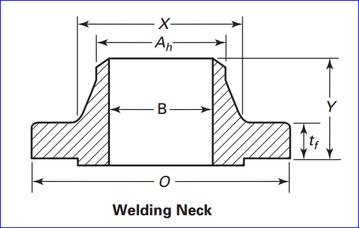
标准ASME B16.5中对焊法兰的相关尺寸如下图所示:

wps_clip_image-30300

Figure 2.1 Welding Neck Flange Dimension

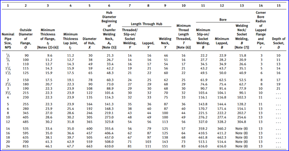
wps_clip_image-17504

Figure 2.2 Dimensions of Class 150 Flanges

以上数据来源为ASME B16.5-2009, Pipe Flanges and Flanged Fittings。ASME is the registered trademark of The America Society of Mechanical Engineers.

3.Flange Modeling

基于OpenCASCADE中Draw Test Harness中的脚本,可以实现上述参数化式的造型,部分Tcl脚本如下所示:

    set dn 15
    set o 
90
    set tf 
9.6
    set x 
30
    set ah 
21.3
    set y 
46
    set b 
15.8
    set r 
3
    set rf 
1.6
       
    
# modeling
    pcylinder aRaisedFace [expr $x/2.0$rf
    pcylinder aFlange [expr 
$o/2.0$tf
    pcone aNeck [expr 
$x/2.0] [expr $ah/2.0] [expr $y-$tf*2.0]
    pcylinder aWeld [expr 
$ah/2.0$tf
    pcylinder aSocket [expr 
$b/2.0] [expr $y+$rf]
    
    nexplode aFlange E
    blend aFlange aFlange 
$r aFlange_2
    
    renamevar aWeld F
    explode F F
    renamevar F E
    explode E E
    chamf aWeld E E_1 F_1 S 
$rf
    
    
# transform to the right position
    ttranslate aFlange 0 0 $rf
    ttranslate aNeck 
0 0 [expr $tf+$rf]
    ttranslate aWeld 
0 0 [expr $y+$rf-$tf]
    
    
# boolean operations
    bop aRaisedFace aFlange
    bopfuse aResultShape
    
    bop aResultShape aNeck
    bopfuse aResultShape
    
    bop aResultShape aWeld
    bopfuse aResultShape
    
    bop aResultShape aSocket
    bopcut aResultShape
    
    
# visualize
    vinit
    vsetgradientbg 
180 200 255 180 180 180 2
    vsetdispmode 
1
    
    vdisplay aResultShape

得到效果如下图所示:

wps_clip_image-4376

Figure 3.1 A Welding Neck Flange DN150

wps_clip_image-23187

Figure 3.2 A Welding Neck Flange DN150

4.Conclusion

综上可知,管件的三维显示效果很逼真,且程序的可扩展性高,方便为后面其他的标准数据的输入。即通过简单的脚本,即可为各种标准的管件建模及可视化。

通过三维模型及尺寸标注,管道设计人员可以轻松查看各种标准的数据。三维逼真的模型显示,给设计人员带来直观感受,增加了趣味性。

年后即将发布程序Pipedata3d,敬请期待。

5. References

1. ASME B16.5-2009. Pipe Flanges and Flanged Fittings. 

2. OpenCASCADE6.8.0. Draw Test Harness User Guide. 2014

3. http://www.wermac.org/


eryar 2015-02-04 20:18 发表评论

pipedata3d User Guide

$
0
0
     摘要: pipedata3d User Guide 1. Introduction 在管道设计过程中,会使用到大量的标准,如ASME,DIN,GB,CB,HG,SH等等。管道设计人员在设计过程中,需要翻阅相关标准手册,查找所需要的数据,较为繁琐。如果能将相关管件的数据以直观的方式展示出来,可以极大地提高管道设计人员的设计效率。 pipedata3d通过把标准数据以表格及三维模型的方式展示出来,更加形象...  阅读全文

eryar 2015-03-03 21:18 发表评论

OpenCASCADE BRepTools

$
0
0
     摘要: OpenCASCADE BRepTools eryar@163.com Abstract. OpenCASCADE BRepTools provides utilities for BRep data structure. OuterWire method to find the outer wire of a face. Dump method to dump a BRep object. It...  阅读全文

eryar 2015-03-14 20:18 发表评论

PDMS RvmTranslator

$
0
0

PDMS RvmTranslator

eryar@163.com

Abstract. AVEVA Review is used for 3D model visualisation for plant or ship design, construction and operation. The RVM file is main input of AVEVA Review. RvmTranslator can translate RVM file to STEP, IGES, STL, etc without Review, only rely on the RVM file.

Key Words. AVEVA  Review, PDMS RVM, STEP, IGES, STL, Data Exchange

1. Introduction

AVEVA Review is a powerful 3D visualization tool for large complex plant and marine models. With features such as walk-through, animation, and high-quality photo-realistic images, AVEVA Review lets you analyse designs and communicate complex ideas easily.

wps_clip_image-24802

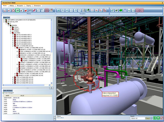
Figure 1. High Performance 3D Visualisation for design, installation, operation & maintenace

Key features of AVEVA Review include:

v High-performance 3D model rendering and walk-through;

v Large model support-effective handling of model files up to 1.1GB;

v High-quality graphical realism with lighting, textures, fog and real-time shadows;

v Advanced animation and avi production tools;

v Object manipulation and clashing;

v Dimensioning;

v Sectioning and Clipping;

v Laser Model Interface for point cloud data;

v 3D export of Review model to Adobe 3D PDF and Autodesk DWF;

v Extensible .NET interface;

wps_clip_image-24806

Figure 2. High quality graphical realism for plant and ship design

wps_clip_image-9316

Figure 3. The AVEVA ReviewShare reader is available as a free download from website

AVEVA Plant/Marine can export RVM file to AVEVA Review, so the RVM file contains all the geometry information. The RvmTranslator can read RVM file and translate to STEP, IGES, STL, etc. And so can exchange model data with other CAD software, such as Autodesk, Solidworks, Pro/e, etc.

2.RvmTranslator Usage

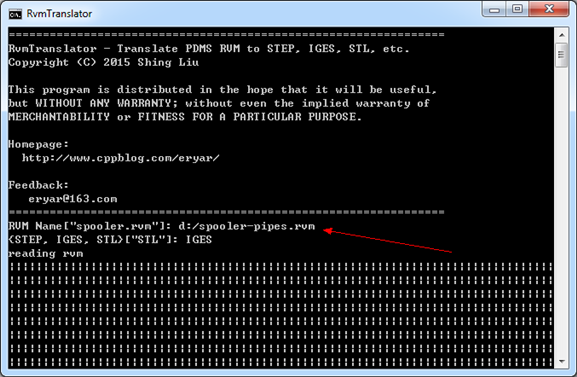
RvmTranslator can translate PDMS RVM to STEP, IGES, STL, etc. The usage of RvmTranslator is easy, after you download the RvmTranslator, run RvmTranslator by RvmTranslator.bat, and input the RVM file name and the export file type, such as STEP, IGES, STL. 

wps_clip_image-10682

Figure 4. RvmTranslator Usage 

There are 2 steps to use RvmTranslator:

v Input the RVM file name;

v Select export file format;

After that you can get the translate result models. You can download the RvmTranslator from the baidu cloud:

Version

Download

RvmTranslator1.0

Download

RvmTranslator2.0

Download

RvmTranslator2.1

Download


3.Translate Result

wps_clip_image-24563

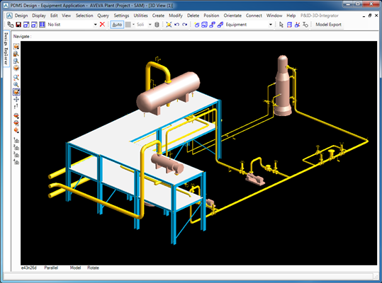
Figure 5. Plant model in AVEVA Design

wps_clip_image-2439

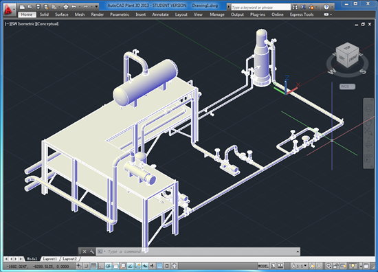
Figure 6. Import Model to AutoCAD

wps_clip_image-2878

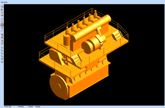
Figure 7. Main Engine in AVEVA Marine

wps_clip_image-8496

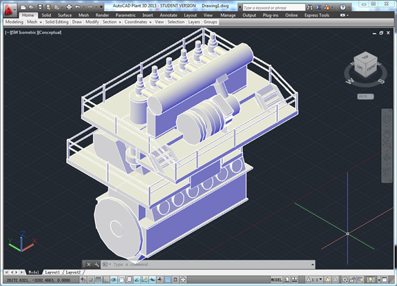
Figure 8. Main Engine imported to AutoCAD

4. Conclusion

The RVM file contains all the geometry model data, so read RVM file and translate to the standard 3D model data exchange file format, such as STEP, IGES, STL, etc. 

Feel free to download the RvmTranslator and have a try, enjoy! :-)

Any suggestion and feedback is welcome, please send email to the author:

eryar@163.com

5. References

1. AVEVA Review: http://www.aveva.com/aveva_review

2. AVEVA Review Release:  http://support.aveva.com/services/products/20212/ub20212.pdf

3. Download RvmTranslator:

http://yun.baidu.com/pcloud/album/file?album_id=3634993082542187183&uk=3808749571&fsid=666228865284234

PDF Version: PDMS RvmTranslator


eryar 2015-04-22 22:37 发表评论

OpenCASCADE PCurve of Topological Face

$
0
0

OpenCASCADE PCurve of Topological Face

eryar@163.com

Abstract. OpenCASCADE provides a class BRepBuilderAPI_MakeFace to build topological faces. A face maybe built from a surface, elementary surface from gp package, surface from Geom, from a wire and find the surface automatically if possible, etc. If a face is built, how to check it for visualization? What does PCurve means? The paper will answer those question.

Key Words. OpenCASCADE, Topological Face, PCurve, Holes

1. Introduction

OpenCASCADE中边界表示法BRep的拓朴面Topological Face包含了完整的几何信息,即给定一个TopoDS_Face,其中包含了边和顶点,而边和顶点包含了几何曲线及三维点。对边和顶点的可视化很好理解:显示顶点就是在场景中绘制一个三维点;显示边最简单的算法可以将边中的曲线在参数空间中等分采样,再将参数对应到曲线上的点连接起来就可以简单显示边了;而面的可视化如何实现呢?

几何造型内核中都有个参数曲线的概念,即PCurve(Parametric Curve),它是实现面可视化的一个很关键的数据。PCurve的定义是参数表示的曲面上的曲线在二维(u, v)参数空间中的二维样条曲线,也就是曲面上的曲线(Curve on Surface)。

在理解PCurve定义的基础上才好对其做进一步的研究,好回答“从哪儿来到哪儿去的问题”,即如何产生PCurve,如何使用生成的PCurve数据。本文主要介绍如何将OpenCASCADE拓朴面中的PCurve可视化,从而方便对拓朴面的检查,也可以看出PCurve在曲可视化方面的应用。PCurve的产生及其他应用有待进一步挖掘。若您对PCurve有何看法,欢迎不吝赐教。


2.PCurve of a Face

由OpenCASCADE中对拓朴形状可视化的算法[2]可知,对面的网格化需要先对面中环,环中的边进行离散化,最后都统一到参数空间,即只需要一个二维网格化算法来对二维的参数空间进行网格化,最后将参数空间网格化的点映射回面中的几何曲面上,即得到曲面的空间网格剖分。

wps_clip_image-29946

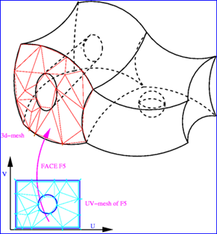
Figure 2.1 Mesh UV domain of a Surface

如上图2.1所示,UV参数空间中的边界线就是拓朴面的环中的边的PCurve,即拓朴面中的环对应了参数空间中的边界,而这些边界的表示就是使用了PCurve。对参数空间进行网格化最常见的算法就是Delaunay三角剖分算法[3],早期OpenCASCADE的版本中使用了一个开源Delaunay库Triangle[4]。通过将曲面在参数空间的结果映射回曲面的三维空间即可将曲面可视化了。如何控制曲面离散精度还有待进一步学习。

wps_clip_image-30572

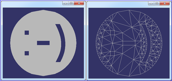
Figure 2.2 A Smiley Face Meshed by Triangle

上图2.2所示为二维三角剖分库Triangle对一个笑脸进行剖分的结果。

在Draw Test Harness中,OpenCASCADE提供了对面的PCurve可视化的命令pcurve。使用pcurve命令可以将一个面中所有的pcurve根据朝向orientation以不同的颜色进行显示。这个命令对检查面中边的朝向的正确性非常有用。下面使用Tcl命令在Draw Test Harness中对基本曲面的PCurve进行显示。

2.1 Plane PCurve

OpenCASCADE中的平面的参数方程为:

wps_clip_image-8180

由上述参数表示的平面方程可知,平面的定义域是无穷的,所以为了生成一个有环的拓朴面,需要对平面设置边界来对无限的平面进行裁剪。相应的Tcl脚本如下所示:

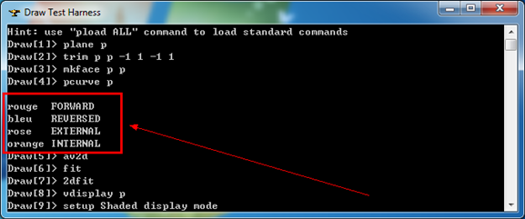
# 1. view the pcurves of a plane face
plane p

# trim the plane to (u,v)->[-1, 1][-1, 1]
trim p p -1 1 -1 1

# make the topo face
mkface p p

# extract the 2d curve of an edge on a face
pcurve p

# display pcurve in 2d viewer
av2d
fit
2dfit

# display face in 3d viewer
vdisplay p

生成结果如下图所示:

wps_clip_image-22514

Figure 2.3 Color for PCurves

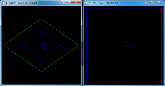
由图2.3可知,pcurve有四种颜色:

v rouge: FORWARD 胭脂红表示正向;

v bleu: REVERSED 蓝色表示反向;(不知道是法语写法还是个错别字,蓝色英语应该为blue)

v rose: EXTERNAL 玫瑰红表示向外;

v orange: INTERNAL 橙黄色表示向内;

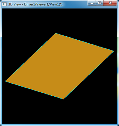
根据上述的颜色规则来看图2.4,可以看出平面边界的pcurves是逆时针闭合的。

wps_clip_image-6057

Figure 2.4 Plane PCurves

wps_clip_image-27675

Figure 2.5 Plane Face in 3D Viewer

2.2 Cylinder PCurve

OpenCASCADE中圆柱面的参数方程为:

wps_clip_image-5104

由上述参数方程可知,u的取值范围是有界的[2, 2pi),v的取值是无限的。所以为了得到有界的拓朴面,至少需要对其v方向进行裁剪。相应的Tcl脚本如下所示:

# 2. view the pcurves of a cylinder face
cylinder c 1

# trim the cylinder to (u,v)->[0, 2pi][0, 1]
trim c c 0 2*pi 0 1

# make the topo face
mkface c c 

# extract the 2d curve of an edge on a face
pcurve c

# display pcurves in 2d viewer
av2d
2dfit
fit

# display face in 3d viewer
vdisplay c

生成结果如下图所示:

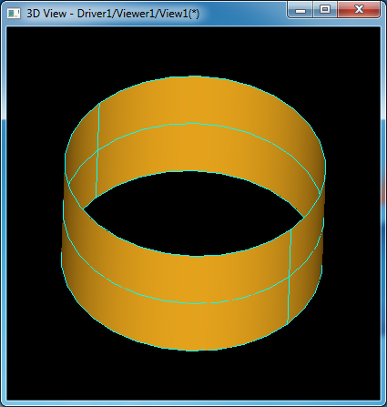
wps_clip_image-19747

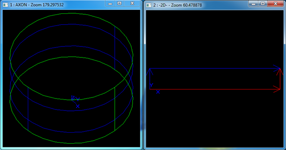
Figure 2.6 Cylinder PCurves

由上图根据pcurve的着色规则可知,圆柱面的pcurves也是按逆时针顺序闭合的。其在三维中的显示结果如下图所示:

wps_clip_image-28392

Figure 2.7 Cylinder Face in 3d Viewer

3.3 Cone PCurve

OpenCASCADE中圆锥面的参数方程为:

wps_clip_image-17202

可知圆锥曲面与圆柱曲面一样,都是在u方向有界,在v方向无界。对其进行裁剪生成拓朴面并显示pcurve的Tcl脚本如下所示:

# 3. view the pcurves of a cone face
cone co 30 0

# trim the cone to (u,v)->[0, 2pi][0, 1]
trim co co 0 2*pi 0 1

# make the topo face
mkface co co

# extract pcurves
pcurve co

# display pcurves in 2d viewer
av2d
2dfit
fit

# display face in 3d viewer
vdisplay co

生成结果如下图所示:

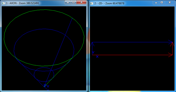
wps_clip_image-29814

Figure 2.8 Cone PCurves

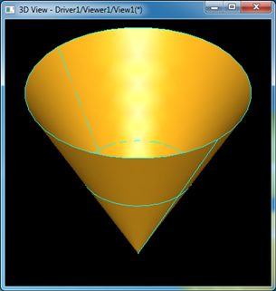
由上图根据pcurve的着色规则可知,圆锥面的pcurves也是按逆时针顺序闭合的。其在三维中的显示结果如下图所示:

wps_clip_image-1397

Figure 2.9 Cone Face in 3D viewer

3.4 Sphere PCurve

OpenCASCADE中球面的参数方程为:

wps_clip_image-5770

由上述参数方程可知,球面在u和v方向均为有界的,所以可不用对其进行裁剪就可生成拓朴面,当然也可对其裁剪得到球面的部分。显示球面pcurves的Tcl脚本如下所示:

# 4. view the pcurves of a sphere face
sphere s 1

# make the topo face
mkface s s 

# extract pcurves
pcurve s

# display pcurves in 2d viewer
av2d
2dfit
fit

# display sphere face in 3d viewer
vdisplay s

生成结果如下图所示:

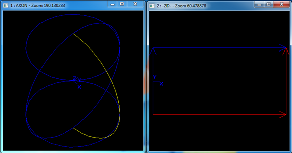
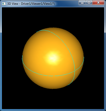
wps_clip_image-16324

Figure 2.10 Sphere PCurves

由上图根据pcurve的着色规则可知,球面的pcurves也是按逆时针顺序闭合的。其在三维中的显示结果如下图所示:

wps_clip_image-29852

Figure 2.11 Sphere in 3d viewer

3.5 Torus PCurve

OpenCASCADE中圆环面的参数方程为:

wps_clip_image-12978

由圆环面的参数方程可知,在参数区间上u和v都是有界的,所以可不用对其进行裁剪就可生成拓朴面,当然也可对其裁剪得到圆环面的部分。显示圆环面pcurves的Tcl脚本如下所示:


# 5. view the pcurves of a torus face
torus t 20 5

# make the topo face
mkface t t

# extract pcurves
pcurve t

# display pcurves in 2d viewer
av2d
2dfit
fit
# display torus in 3d viewer
vdisplay t

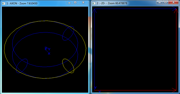
生成结果如下图所示:

wps_clip_image-22530

Figuer 2.12 Torus PCurves

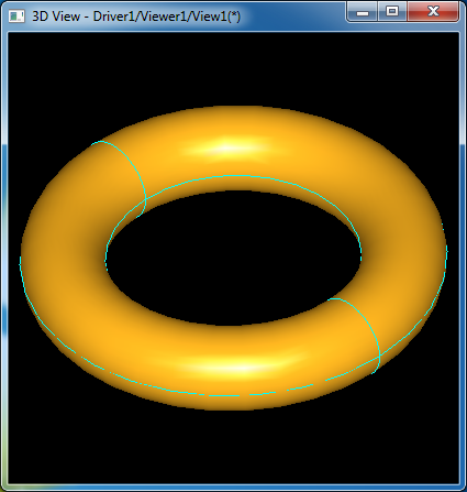
由上图根据pcurve的着色规则可知,圆环面的pcurves也是按逆时针顺序闭合的。其在三维中的显示结果如下图所示:

wps_clip_image-10501

Figure 2.13 Torus in 3d viewer

3.PCurve of a Face With Holes

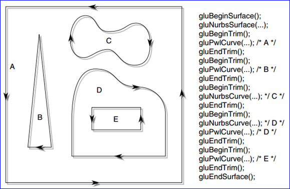
由OpenGL编程指南[10]可知,要对一个NURBS曲面进行裁剪,可以创建gluPwlCurve和gluNurbsCurve来在参数空间形成闭合区域。其中gluPwlCurve创建是多段直线,而gluNurbsCurve生成的是在单位参数空间的NURBS曲线。创建裁剪曲线时需要考虑曲线的朝向(orientation),即曲线是顺时针的还是逆时针的。曲线裁剪曲面的方式很简单,想像你沿着曲线走,左手边的将会被保留,右手边的将会被去除。

wps_clip_image-29949

Figure 3.1 Parametric Trimming Curves

裁剪曲线还必须闭合且不能自交(Trimming curves must be closed and nonintersecting)。这里的裁剪曲线与OpenCASCADE中的参数曲线pcurve的概念相同。OpenCASCADE中的面也是采用的相同的规则。下面通过Tcl脚本来测试OpenCASCADE中带有开孔的面的pcuve是否满足OpenGL中裁剪曲面的规则。

# test face with one hole
plane p
trim p p 
-10 10 -10 10
mkface p p
pcylinder c 
1 2

bop p c
bopcut s

vdisplay s

explode s F
pcurve s_1

av2d
2dfit
fit

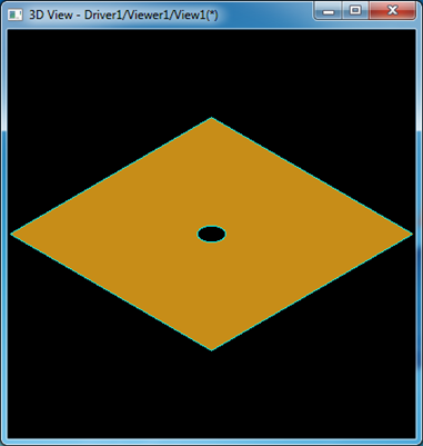
上述Tcl脚本为将一个平面用圆柱去挖一个孔,如下图所示:

wps_clip_image-8553

Figure 3.2 Face with a Hole

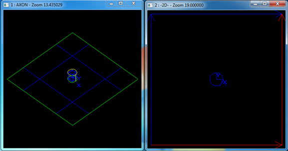
遍历被挖孔(boolean operation)得到的形状的面,得到一个面,显示这个面的pcurve如下图所示:

wps_clip_image-26044

Figure 3.3 PCurve of a Face with one hole

由上图3.3可知,pcurve的规则与OpenGL中的裁剪曲线一致。孔的pcurve为蓝色,即为逆时针的反向:顺时针。当一个面上生成多个孔时,是否仍然满足上述规则呢?下面使用Tcl来对验证一下:

# test pcurve of a face with multi-holes
sphere s 10
mkface s s

pcylinder c1 
1 30
pcylinder c2 
1 30

ttranslate c1 
-5 -5 -15
ttranslate c2 
5 5 -15

bop s c1
bopcut s

bop s c2
bopcut s

explode s F
pcurve s_1

av2d
2dfit
fit

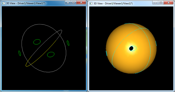
用脚本在一个球面上生成四个孔,如下图所示:

wps_clip_image-13810

Figure 3.4 A sphere face with 4 holes

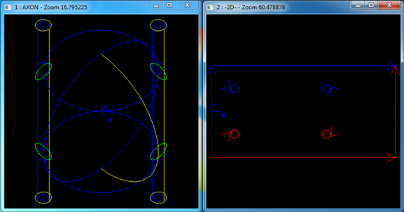
遍历boolean operation生成孔后的形状的面,可看到只生成了一个面。将这个面的pcurve显示出来如下图所示:

wps_clip_image-16372

Figure 3.5 PCurves for a sphere with 4 holes

由上图3.5可知,pcurve的朝向也与OpenGL中裁剪曲线的朝向一致。当一个面生成的开孔如图3.1中的D和E时,在OpenCASCADE中是如何表示的呢?下面也有Tcl脚本测试测试:

plane p
trim p p 
-10 10 -10 10
mkface p p

ptorus t 
5 1

bop p t
bopcut s

vdisplay s

explode s F
pcurve s_1
pcurve s_2

av2d
2dfit
fit

生成结果如下图所示:

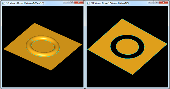
wps_clip_image-31602

Figure 3.6 A Plane cut a Torus

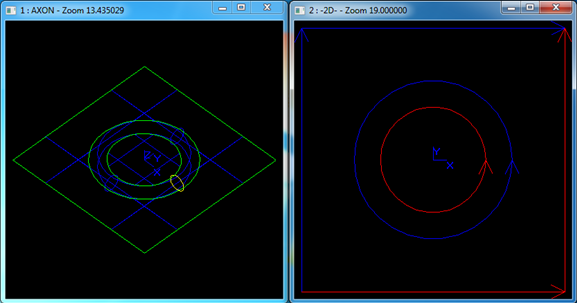
wps_clip_image-8216

Figure 3.7 PCurves for the faces

由上图可知,当一个平面去掉一个圆环面后,生成了两个面,与有些几何内核的用链表来将结果表示成一个面不同,OpenCASCADE中将结果生成了两个面。其pcurves的朝向也与OpenGL中的裁剪曲线的朝向一致。

4.Conclusion

综上所述,曲面上的曲线pcurve的概念是一个非常重要的概念,理解pcurve对造型及可视化有着重要意义。本文结合OpenGL中裁剪曲线的规则及OpenCASCADE的Draw Test Harness中显示拓朴面pcurve的命令,来对基本曲面及裁剪曲面的pcurve的朝向进行检验。掌握了这些规则,可方便对自己构造拓朴面的正确性进行检验。

5. Acknowledge

时光荏苒,从毕业到现在不经意间就到了而立之年。沧海桑田,岁月蹉跎,经历春夏秋冬的四季,品尝酸甜苦辣的人生。感谢一路走来,亲人、朋友、同事等对给予我的支持,信任和鼓励,让我可以做自己喜欢的事情,找到人生的方向。

寄蜉蝣与天地,渺沧海之一粟。准备回到离家近的武汉工作,切换到生活模式,多些时间陪伴父母亲人,以报养育之恩。

6. References

1. Shing Liu. PCurve - Curve on Surface. 

http://www.cnblogs.com/opencascade/p/3601859.html

2. Shing Liu. Topology and Geometry in OpenCASCADE-Edge.

http://www.cnblogs.com/opencascade/p/3604052.html

3. Topology and Geometry in OpenCASCADE-Face.

http://www.cnblogs.com/opencascade/p/3605729.html

4. Shing Liu. Mesh Algorithm in OpenCASCADE.  http://www.cnblogs.com/opencascade/p/3648532.html

5. Shing Liu. Delaunay Triangulation in OpenCASCADE. 

http://www.cppblog.com/eryar/archive/2013/05/26/200605.aspx

6. Shing Liu. Triangle-Delaunay Triangulator. 

http://www.cnblogs.com/opencascade/p/3632705.html

7. OpenCASCADE, Draw Test Harness User Guide.

8. OpenCASCADE, BRep Format White Paper.

9. Richard S. Wright Jr., Benjamin Lipchak. OpenGL SuperBible. Sams Publishing. 2004

10. Dave Shreiner. OpenGL Programming Guide. Addison-Wesley. 2009


eryar 2015-04-25 12:22 发表评论

AVEVA RvmTranslator

$
0
0

AVEVA RvmTranslator

eryar@163.com

AVEVA的RVM文件格式包含了三维模型数据及其他信息,可用于工厂模型的浏览、评审等。常见的三维浏览及评审软件如Autodesk的Navisworks、Intergraph的评审软件SmartPlant Review Publisher等,都提供了对RVM格式的支持。

AVEVA的RVM格式分为两种:文本格式的和二进制格式的。因为文本格式的很简单,二进制格式的RVM格式的解析可参考:

http://www.cnblogs.com/SudoSky/p/4456806.html

RvmTranslator主要将RVM文件中的三维模型数据转换成常见的三维数据交换格式STEP、IGES、STL等,主要用于与其他CAD系统进行数据交换,如Autodesk 3dMax、Pro/E、SolidWorks等。RvmTranslator的主要功能如下:

Input

Support

文本格式的RVM文件 (Text RVM)

二进制格式的RVM文件(Binary RVM)

RvmTranslator可以导出的三维模型数据交换格式:

Output

Support

STEP

IGES

STL

DXF

To be supported


RvmTranslator运行环境要求

因为数据转换涉及一些计算,所以对电脑的要求较高。推荐最低配置如下表所示:

Operating System

Windows 8 / 7 / Vista / XP

CPU

Intel i5

RAM

8GB

Free Disk Space

100MB


RvmTranslator下载试用

Version

Download

RvmTranslator1.0

Download

RvmTranslator2.0

Download

RvmTranslator2.1

Download


转换结果示例:

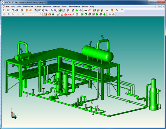
wps_clip_image-7083

Figure 1. Plant Model in PDMS

wps_clip_image-25656

Figure 2. Plant Model in AutoCAD

wps_clip_image-14037

Figure 3. Plant Model in HOOPS

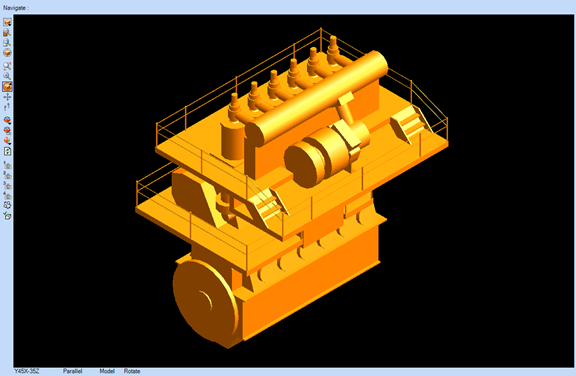
wps_clip_image-31711

Figure 4. Main Engine Model in AVEVA Marine

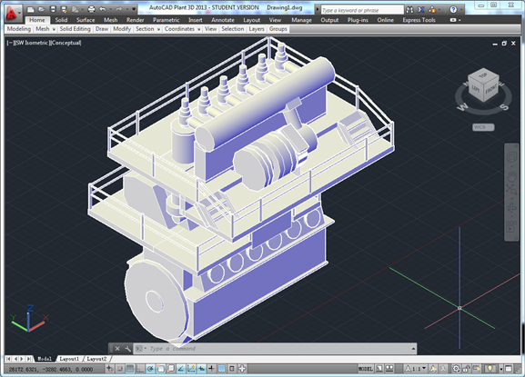
wps_clip_image-28940

Figure 5. Main Engine Model in AutoCAD

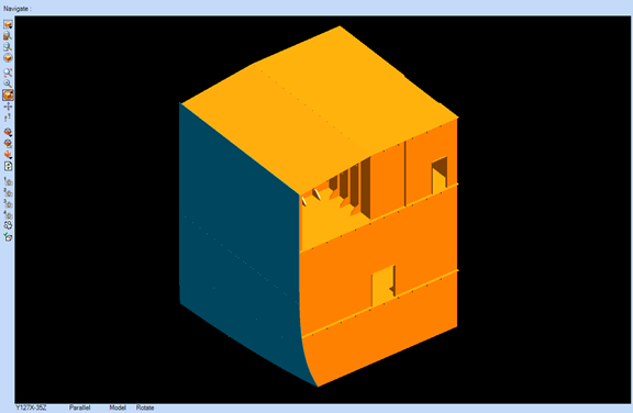
wps_clip_image-5078

Figure 6. Hull Model in AVEVA Marine

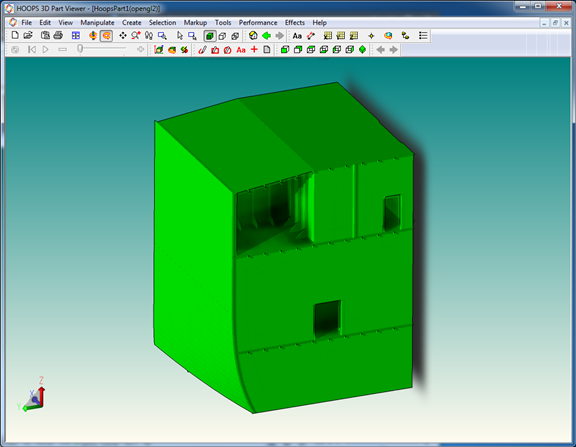
wps_clip_image-30451

Figure 7. Hull Model in HOOPS

PDF Version AVEVA RvmTranslator


eryar 2015-05-04 20:13 发表评论

Use Qt in Debian for OpenCASCADE

$
0
0

Use Qt in Debian for OpenCASCADE

eryar@163.com

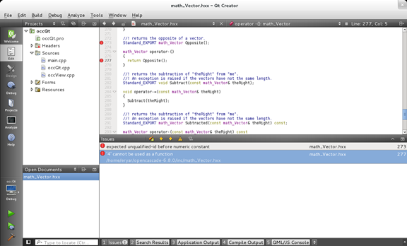
Recently several OpenCASCADE enthusiasts want to build my simple Qt demo about OpenCASCADE on ubuntu system, but could not compile it successfully. Because I only compiled the occQt in Windows system, do not try it in Linux system. I try to build it on Debian system, also have the same errors as follows:

wps_clip_image-9806

Figure 1. Compile errors of Building occQt on Debian

In order to use Qt5 in Debian7, you can input the following commands:

1. Get Qt5 on Debian:

sudo apt-get install qt5-default qt5-qmake qtbase5-dev-tools qtchooser

2. Download the newest version of QtCreator from Qt website:

http://www.qt.io/download-open-source/#section-6

You can get the following file:

qt-creator-opensource-linux-x86_64-3.4.0.run

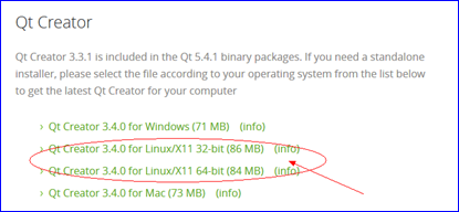
wps_clip_image-22633

Figure 2. Download Qt Creator for Linux

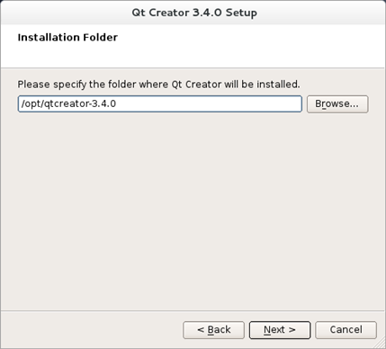
3. Install QtCreator manually:

Install Qt Creator manually by the following commands:

chmod u+./qt-creator-opensource-linux-x86_64-3.4.0.run

./qt-creator-opensource-linux-x86_64-3.4.0.run

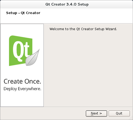
wps_clip_image-16257

Figure 3. Qt Creator Setup

wps_clip_image-3440

Figure 4. Qt Creator Setup

4. It is succeed When the Qt Creator Icon appears in the Applications.

wps_clip_image-26540

Figure 5. Qt Creator in Applications

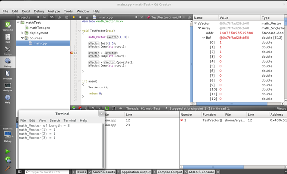
5. I tried the math_Vector, it runs correctly, the code list as follows:

#include <math_Vector.hxx>

void TestVector(void)
{
    math_Vector aVector(
13);

    aVector.Init(
1.0);
    aVector.Dump(std::cout);

    aVector 
= -aVector;
    aVector.Dump(std::cout);

    aVector 
= aVector.Opposite();
    aVector.Dump(std::cout);

}

int main()
{
    TestVector();

    
return 0;
}

The configuration of the test project as follows:

TEMPLATE = app

CONFIG 
+= console

CONFIG 
-= app_bundle

CONFIG 
-= qt

SOURCES 
+= main.cpp

include(deployment
.pri)

qtcAddDeployment()

INCLUDEPATH 
+= /home/eryar/opencascade-6.8.0/inc

DEPENDPATH 
+= /home/eryar/opencascade-6.8.0

LIBS 
+= -L/home/eryar/opencascade-6.8.0/lib/ -lTKernel -lTKMath

The result shows:

wps_clip_image-25550

Figure 6. Test math_Vector in Qt on Debian

It can compile and run correctly, the compile error in occQt do not appear in the test program. you can also debug the code in Qt Creator. So use Qt Creator to program on Linux is very convenient.


eryar 2015-05-21 22:10 发表评论

A Simple OpenGL Shader Example

$
0
0

A Simple OpenGL Shader Example

eryar@163.com

Abstract. OpenGL Shading Language, the high-level programming language defined to allow application writers to write programs that execute on the programmable processors defined within OpenGL. Informally the language is sometimes referred to as GLSL. The GLSL has been made part of the OpenGL standard as of OpenGL2.0. The paper focus on a simple example of OpenGL Shader, which can be used as a guide of GLSL.

Key Words. OpenGL, OpenGL Shading Language, GLSL, Shader, Qt


1. Introduction

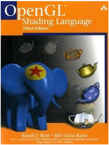
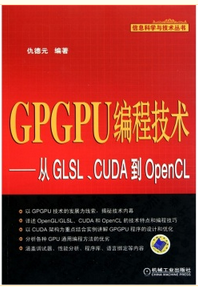
很早之前,从网上下载到这么一本书《OpenGL Shading Language》,翻看了几遍,终不得要领。后来看到一本由仇德元编写的《GPGPU编程技术—从GLSL、CUDA到OpenCL》,对GPU的了新的认识,对其性能刮目相看。书中给出的一个简单例子,也便于对Shader的入门。

wps_clip_image-22807 wps_clip_image-16315

Figure 1.1 OpenGL Shading Language and GPGPU

从OpenGL Shading Language的出现可以发现程序员的一个特点,那就是不喜欢一成不变的东西,希望自己有更多的控制权,有个性,向往自由。如果要有个性,那就要引入这个新的东西GLSL了,增加了学习成本。不过从OpenGL2.0之后,Shader已经成了OpenGL标准的一部分,新版的OpenGL的书籍中都少不了shader的内容。Shader成了真实感图形、高性能计算中不可或缺的技术,学习掌握新的工具是为了生活更轻松。

为了让例子简单,本文在Qt中实现了一个简单的Shader示例,通过这个例子入门后,再结合《OpenGL Shading Language》去实现更炫的效果。再者就是去理解OpenCASCADE中的shader应用。

2.OpenGL operation pipeline

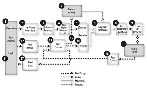
原来有个问题一直困扰着我,那就是三维的模型怎么在二维的计算机屏幕上显示的。现在明白了这个就其实是显卡的主要工作,并按一定的流水线来实现的。图形流水线(pipeline)是GPU工作的通用模型,它以某种形式表示的三维场景为输入,输出二维的光栅图像(raster images),也就是位图。这样三维的模型就可以在二维的屏幕上进行显示了。下面依次解释流水线中的关键步骤:

v 图形流水线的起点是一个三维模型。这个三维模型可以是用软件设计出的三维游戏人物,也可以是逆向工程(Reverse Engineering)中用激光扫描仪(Laser Scanner)设备采集的顶点,也可以是几何造型内核(如OpenCASCADE)将模型网格化生成的顶点等。不论何种模型,在计算机处理之前都一定要经过采样而得到有限的离散顶点,每个顶点都可以被一个向量描述为一个三维坐标系里的点。这些可用来描述三维顶点组成了点云(Point Cloud)。如果采样频率足够高,得到的顶点就可以细致地描述模型的表面。点云中的点可以由一个列表表示,列表中每一项是某点的三维坐标值。同时,列表中每一点都带有该点的颜色信息。这个顶点列表即是流水线的输入数据,从起点进入流水线。

v 顶点可以用来形成多边形,从而拟合出近似的表面。由顶点形成多边形最常用的一种方法是三角化(triangulation),即每相邻的三个点组成一个三角形。接下来每个顶点要经过一系列的逐顶点操作(per-vertex operation),比如计算每个顶点的光照、坐标变换等。

v 由于显示输出的需要,用户会定义一个视口(viewport),即观察模型的位置和角度。然后,模型被投影到与视口观察方向垂直的平面上。这个投影变换也是硬件加速的。根据视口的大小,投影结果有可能被裁剪(clipping)掉一部分。

v 接受模型投影的平面是一个帧缓存(frame buffer),它是一个由像素(pixels)定义的光栅化平面。光栅化(rasterization)的过程,实际上就是决定帧缓存上的哪些像素该取怎么样的值。通过采样和插值,光栅化器(rasterizer)会决定一幅最接近原投影图像的位图。

v 这些像素或者由像素连成的片段还须经历一些逐片段操作(per-fragment operation),也就是说它们的颜色也可以根据算法改变。另外纹理映射(texturing or texture mapping)在这一阶段也会覆盖某些像素的值。对于投影和光栅化的结果,还要判断片段的可见性,也就是遮挡探测(occlusion detection)。

v 最后帧缓存里面的结果被刷新到显示器上。该过程以较高的频率重复,因为人的视频延迟,感觉到的就是连续的。

wps_clip_image-15682

Figure 2.1 A simplified version of the OpenGL pipeline

wps_clip_image-24778

Figure 2.2 Overview of OpenGL operation

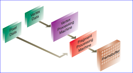
可以将上述OpenGL的渲染管线想成有两个机器来完成主要的工作:一个机器处理顶点;一个处理片段。对于早期的OpenGL而言,只是两个机器是内置的,程序员不能改变他们的工作方式。

wps_clip_image-20622

Figure 2.3 The OpenGL Fixed-Function Pipeline[3]

然而可编程的Shader(programmable shader)则是可以对这两个机器的工作进行干预。

3.Using GLSL Shaders

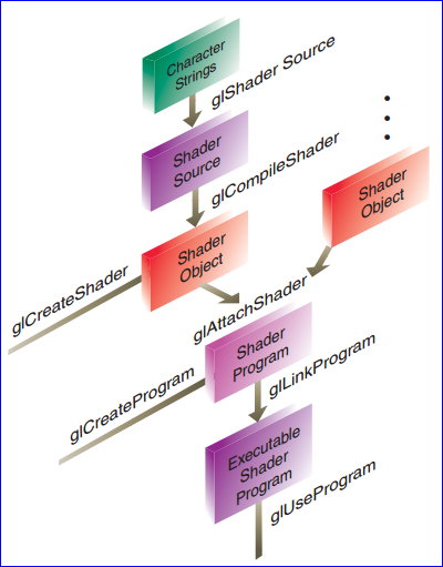
当你想在程序中使用一个顶点Shader或片段Shader时,需要按如下步骤进行:

v 创建一个Shader对象;

v 将Shader的源文件编译到这个对象;

v 验证源文件是否编译成功;

然后将这些shader链接到一个Shader程序:

v 创建一个Shader程序;

v 将创建的Shader对象绑定到这个Shader程序;

v 链接Shader程序;

v 验证链接是否成功;

v 将shader对象应用到顶点及片段的处理;

如下图所示:

wps_clip_image-9757

Figure 3.1 Shader Creation Flowchart

4.The simplest Shader Example

本来想用glut来写个简单的例子的,但是识别不了glCreateShader这种函数,发现要下载一些第三方库才可以,如glew。看到Qt中已经有封装好的QGLShader和QGLShaderProgram,所以还是决定用Qt来写个简单的例子,从而来对OpenGL的shader有个感性的认识。其中关于Shader部分的主要是这个函数:

void ShaderWidget::setShader()
{
    
if (!isValid())
    {
        
return;
    }

    
const QGLContext* aGlContext = context();

    QGLShaderProgram
* aShaderProgram = new QGLShaderProgram(aGlContext);

    aShaderProgram
->addShaderFromSourceFile(QGLShader::Vertex, "vertex.vert");
    aShaderProgram
->addShaderFromSourceFile(QGLShader::Fragment, "fragment.frag");

    aShaderProgram
->link();
    aShaderProgram
->bind();
    QString aLog 
= aShaderProgram->log();
}

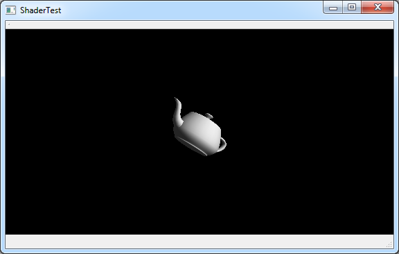
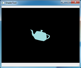
先看一下没有使用Shader之前的程序的效果图:

wps_clip_image-23309

Figure 4.1 A teapot model without shader

其中添加两个shader,一个是vertex shader: vertex.vert,一个是fragment shader:fragment.frag。在vertex shader中对顶点的坐标进行变换,代码如下所示:

void main()
{
    vec4 a 
= gl_ModelViewProjectionMatrix * gl_Vertex;
    gl_Position.x 
= 0.4 * a.x;
    gl_Position.y 
= 0.1 * a.y;
}

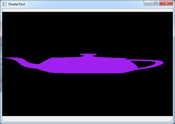
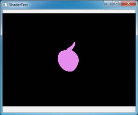
OpenGL内置变量gl_Position保存了当前顶点的位置信息,上面的顶点着色器修改了每个顶点的X坐标和Y坐标,使得输出了一个扭曲的teapot。

片段着色器当前片段的颜色改成紫色,片段着色器代码如下:

void main()
{
    gl_FragColor 
= vec4(0.6270.1250.9411.0);
}

为了验证程序是使用了着色器,运行程序得到如下图所示:

wps_clip_image-28370

Figure 4.2 A Teapot with shader

在不重新编译程序的情况下,只修改片段着色器中的代码,改成如下所示内容:

void main()
{
    gl_FragColor 
= vec4(0.6270.1250.01.0);
}

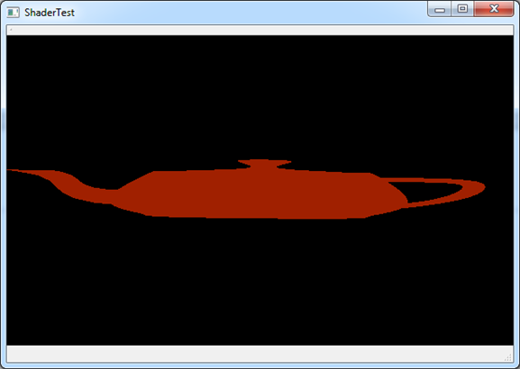
保存片段着色器代码后直接运行程序,可得到如下图所示的红色teapot:

wps_clip_image-24948

Figure 4.3 Change Fragment Shader

可以看到shader的确是起了作用。本文最后将给出程序的完整代码及shader的代码,便于测试。

5.Conclusion

OpenGL的Shader给了程序员对OpenGL的更多的控制权,可对其顶点处理和片段处理进行更个性化的配置以达到炫酷的效果。

Shader的使用步骤是先创建shader对象,再将源码编译到shader对象。最后通过shader程序,将shader添加并编译、链接和使用。

最后在Qt中以一个简单的例子来验证了shader的效果,入门之后便于理解GLSL更详细的功能,以使自己的可视化程序具有更高的性能,更酷的效果。

6. References

1. 仇德元. GPGPU编程技术—从GLSL、CUDA到OpenCL. 机械工业出版社. 2012

2. Randi J. Rost. OpenGL Shading Language. Addison Wesley. 2006

3. Dave Shreiner. OpenGL Programming Guide(7th). Addison-Wesley. 2009


Source Code and PDF Version: A Simple OpenGL Shader Example


eryar 2015-06-27 21:38 发表评论

Make Helix Curve in OpenCASCADE

$
0
0

Make Helix Curve in OpenCASCADE

eryar@163.com

Abstract. OpenCASCADE does not provide helix curve directly, but you can build a helix curve by the pcurve of a surface(curve on surface). When you understand the pcurve of a surface, you can make a helix curve easily. The paper first make a helix by Tcl in Draw Test Harness, then translate the Tcl script to OpenCASCADE C++ code.

Key Words. OpenCASCADE, Helix Curve, PCurve, Sweep, Spring


1. Introduction

螺旋线是实践中常用到的曲线,例如平头螺丝钉的外缘曲线就是螺旋线。当我们拧紧平头螺丝钉时,它的外缘曲线上的任一点M一方面绕螺丝钉的轴旋转,另一方面又沿平行于轴线的方向前进,点M就走出一段螺旋线。[1]

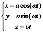
如果空间一点M在圆柱面x*x+y*y=a*a上以角速度ω绕z轴旋转,同时又以线速度υ沿平等于z轴正方向上升(其中ω,υ都是常数),那未点M构成的图形叫螺旋线。其参数方程为:

wps_clip_image-3353

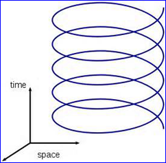
wps_clip_image-14885

Figure 1.1 A Helix Curve

OpenCASCADE中并没有直接提供构造螺旋线的类和函数,因此只有自己来构造了,其中构造的核心是要理解PCurve(曲面的参数曲线)。本文先以Tcl脚本在Draw Test Harness中快速生成一个螺旋线,再将相应的Tcl脚本转换成C++代码。在理解Pcurve概念的基础上来构造螺旋线还是很简单的,甚至还可以扩展应用。

2.Make Helix Curve

在OpenCASCADE提供的一个经典例子:生成一个酒瓶中,就有螺旋线的应用,即生成瓶口处的螺纹。当时看这例子的时候也是没有完全理解,究竟怎么生成的那个螺旋线?感谢lifenli的提醒,使我又重温了一遍例子,顿时茅塞顿开,明白了pcurve的一个应用。

由《OpenCASCADE BRep Format》[4]中可知,圆柱面的参数方程为:

wps_clip_image-29114

假设当你在参数空间[u,v]中创建一条二维曲线后,可根据这个二维曲线来计算对应曲面上的三维曲线。根据二维曲线的不同定义,得到的结果如下:

条件

参数方程

参数曲线

U=0

S(v)=P+r*cos(u)+vDz

与Z轴平行的直线

V=0

S(u)=P+r*(cos(u)*Dx+sin(u)*Dy)

与XOY面平行的圆

U!=0 && V != 0

S(u,v)=P+r(cos(u)*Dx+sin(u)*Dy)+vDz

螺旋线

对比螺旋线的参数方程可知,当参数空间中的u和v都不为0时,得到的圆柱面上的线就是螺旋线。考虑最简单的情况,那就是u=v,即在参数空间中是一条斜率k=1的直线。在OpenCASCADE的Draw Test Harness用Tcl脚本测试,Tcl脚本如下所示:
#
# make helix curve in OpenCASCADE.
# Shing Liu(eryar@163.com)
# 2015-07-08 22:00
#


pload MODELING VISUALIZATION

cylinder aCylinder 
6

line aLine2d 
0 0 1 1
trim aSegment aLine2d 
0 2*pi

mkedge aHelixEdge aSegment aCylinder 
0 6*pi

vdisplay aHelixEdge
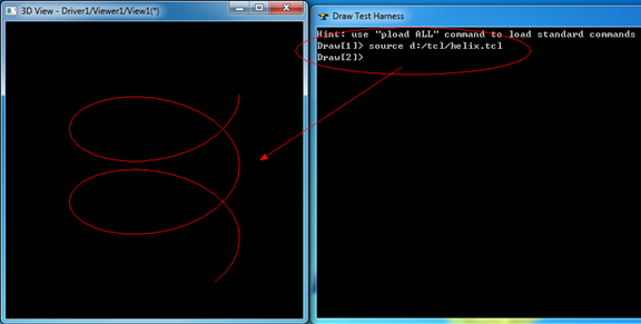
代码先加载所需的造型及显示模块,然后创建一个圆柱面aCylinder;一条二维直线aLine2d;再将参数范围限定在0到2PI之间;最后使用了用曲面及其上的pcurve来创建边的算法mkedge生成了螺旋线并显示在三维窗口中。

wps_clip_image-9019

Figure 2.1 Make a helix by Tcl script

上述Tcl脚本可以很容易的转换成C++代码的,下面给出相应的C++实现,源码如下所示:


#define WNT

#include 
<gp_Lin2d.hxx>

#include 
<GCE2d_MakeSegment.hxx>

#include 
<Geom_CylindricalSurface.hxx>

#include 
<BRepBuilderAPI_MakeEdge.hxx>

#include 
<TopoDS_Edge.hxx>

#include 
<BRepTools.hxx>

#pragma comment(lib, 
"TKernel.lib")
#pragma comment(lib, 
"TKMath.lib")
#pragma comment(lib, 
"TKG3d.lib")
#pragma comment(lib, 
"TKBRep.lib")
#pragma comment(lib, 
"TKGeomBase.lib")
#pragma comment(lib, 
"TKTopAlgo.lib")


void makeHelix(void)
{
    Handle_Geom_CylindricalSurface aCylinder 
= new Geom_CylindricalSurface(gp::XOY(), 6.0);

    gp_Lin2d aLine2d(gp_Pnt2d(
0.00.0), gp_Dir2d(1.01.0));

    Handle_Geom2d_TrimmedCurve aSegment 
= GCE2d_MakeSegment(aLine2d, 0.0, M_PI * 2.0);

    TopoDS_Edge aHelixEdge 
= BRepBuilderAPI_MakeEdge(aSegment, aCylinder, 0.06.0 * M_PI).Edge();

    BRepTools::Dump(aHelixEdge, std::cout);

    BRepTools::Write(aHelixEdge, 
"d:/helix.brep");
}

int main(int argc, char* argv[])
{
    makeHelix();

    
return 0;
}

由C++代码可知,生成螺旋线的关键是在生成边的时候,将pcurve和相应的曲面及其参数范围一起传给了生成边的类,这样就得到拓朴边了。如果想要得到几何的螺旋线,可以使用工具BRep_Tool::Curve()来将拓朴边中的几何曲线提取出来。经过测试,用pcurve生成的Edge中没有三维几何曲线,不过occ提供了一个静态函数来将pcurve对应的三维曲线拟合成nurbs曲线,函数为:BRepLib::BuildCurve3d();

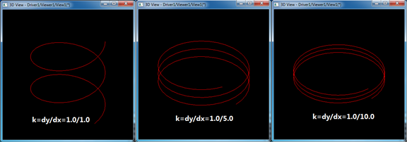
参数空间中pcurve的斜率决定了螺旋线的螺距pitch,当其他参数不变,改变斜率后得到如下图所示结果:

wps_clip_image-2214

Figure 2.2 Different Pitch by different K

由图可知,当pcurve的斜率越小时,得到的螺旋线的螺距也越小。修改pcurve的斜率只需要修改上述Tcl脚本中的aLine2d的斜率。

如当斜率k=1时的pcurve为:

line aLine2d 0 0 1 1

当斜率k=1.0/5.0时的pcurve为:

line aLine2d 0 0 5 1

当斜率k=1.0/10.0时的pcurve为:

line aLine2d 0 0 10 1

可以自己尝试修改看看没的斜率得到的不同螺旋线的螺距变化。

3.Spring: Sweep profile along helix

得到螺旋线后自然就想到能不能用一个圆沿着螺旋线来放样,从而得到一个弹簧。下面还是用Tcl脚本在Draw Test Harness中尝试一下,相应的C++实现也是很容易找到相关的类。


#
# make helix curve in OpenCASCADE.
# Shing Liu(eryar@163.com)
# 2015-07-08 22:00
#


pload MODELING VISUALIZATION

cylinder aCylinder 
6

line aLine2d 
0 0 1 1
trim aSegment aLine2d 
0 2*pi

mkedge aHelixEdge aSegment aCylinder 
0 6*pi

# there is no curve 3d in the pcurve edge.
mkedgecurve aHelixEdge 0.001

wire aHelixWire aHelixEdge

circle profile 
6 0 0 0 4 1 1
mkedge profile profile
wire profile profile
mkplane profile profile

pipe aSpring aHelixWire profile

vdisplay aSpring
vsetmaterial aSpring steel
vsetgradientbg 
180 200 255 180 180 180 2
vsetdispmode 
1
vzbufftrihedron

# set ray tracing
if { ! [catch {vrenderparams -raytrace -shadows -reflections -fsaa -rayDepth 5}] } {
    vtextureenv on 
1
}

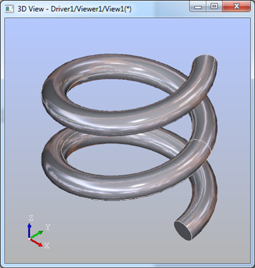
生成效果如下图所示:

wps_clip_image-8846

Figure 3.1 Spring by sweep a circle along a helix path

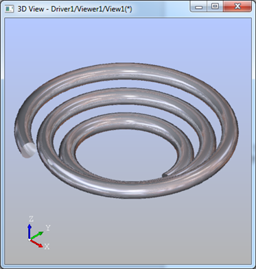
当将pcruve在圆锥面上生成三维曲线时就会得到类似夏天的蚊香那样螺旋形状。同样使用上述代码,只是将圆柱面改成圆锥面得到:

wps_clip_image-3726

Figure 3.2 Mosquito Coil

4.Conclusion

综上所述,常见的计算几何造型书中讲到曲线的参数方程都会以螺旋线为经典例子,甚至是高等数学中也是一样,由此可见螺旋线是很常见的一种曲线。但是occ中并没有直接提供螺旋线的几何曲线,只有通过pcurve来构造了。所以理解pcurve后,才好理解make bottle例子中的瓶颈螺纹部分的代码。

通过将一个轮廓沿着螺旋线扫掠可以得出很多有意思的模型。在使用sweep的过程中发现pcurve生成的边Edge中并没有三维几何曲线,所以会导致算法失败。最终发现occ提供了一个将pcurve生成的边中生成出一个拟合三维几何曲线的函数BRepLib::BuildCurve3d()。对于一些在曲面上的曲线的造型可以参考这种用法,用pcurve来构造。

5. References

1. 同济大学数学教研室. 高等数学(上). 高等教育出版社. 1978

2. Helix. http://mathworld.wolfram.com/Helix.html

3. OpenCASCADE Make Bottle Tutorial. 2015

4. OpenCASCADE BRep Format. 2015

5. 莫勇,常智勇. 计算机辅助几何造型技术. 科学出版社. 2009


PDF Version and Tcl Script Make Helix Curve in OpenCASCADE


eryar 2015-07-09 21:52 发表评论

A Simple OpenGL Shader Example II

$
0
0

A Simple OpenGL Shader Example II

eryar@163.com

Abstract. The OpenGL Shading Language syntax comes from the C family of programming languages. Tokes, identifiers, semicolons, nesting with curly braces, control-flow, and many key words look like C. GLSL provides three qualifiers which form the interfaces of the shaders to their outside world. 

Key Words. OpenGL, GLSL, Qualifiers, 

1. Introduction

GLSL的特性与C/C++非常类似,包括它的数据类型。GLSL有三种基本数据类型:float, int和bool,及由这些数据类型组成的数组和结构体。需要注意的是GLSL并不支持指针。

GLSL中有4个限定符(Qualifier)可供使用,它们限定了被标记的变量不能被更改的“范围”。及通过这几个限定符可以与OpenGL的程序来通信,即为OpenGL程序提供了一个将数据传递给Shader的界面(Interface to a Shader)。

OpenCASCADE中使用GLSL实现了Ray Tracing效果,刚开始使用第三方库OpenCL来使用GPU加速,最新版本统一使用GLSL。

wps_clip_image-26489

Figure 1.1 OpenGL Training

在《OpenGL高级编程技术培训教材》中,GLSL也是一个重要内容。虽然当时听得云里雾里,还是要感谢公司提供这样的培训机会。

2.GLSL Data Types

  GLSL内置了许多数据类型,使图形操作的表达式计算更方便。布尔类型、整型、矩阵、向量及结构、数组等都包括在内。

Scalars

float

Declares a single floating-point number.

int

Declares a single integer number.

bool

Declares a single Boolean number.

这三种是GLSL的基本类型。

Vectors

vec2

Vector of two floating-point numbers

vec3

Vector of three floating-point numbers

vec4

Vector of four floating-point numbers

ivec2

Vector of two integers

ivec3

Vector of three integers

ivec4

Vector of four integers

bvec2

Vector of two booleans

bvc3

Vector of three booleans

bvc4

Vector of four booleans

向量非常有用,可以用来存储和操作颜色、位置、纹理坐标等等。GLSL内置的很多变量及函数中就大量使用了向量。

Matrices

mat2

2x2 matrix of floating-point numbers

mat3

3x3 matrix of floating-point numbers

mat4

4x4 matrix of floating-point numbers

矩阵主要用来实现线性变换。

Samplers

sampler1D

Accesses a one-dimensional texture

sampler2D

Accesses a two-dimensional texture

sampler3D

Accesses a three-dimensional texture

samplerCube

Accesses a cube-map texture

sampler1DShadow

Accesses a one-dimensional depth texture with comparison

sampler2DShadow

Accesses a two-dimensional depth texture with comparison


3.Qualifiers


GLSL有4个限定符可供使用,它们限定了被标记的变量不能被更改的范围:

Qualifiers

attribute

For frequently changing information, from the application to a vertex shader

uniform

For infrequently changing information, from the application to either a vertex shader or a fragment shader

varying

For interpolated information passed from a vertex shader to a fragment shader

const

For declaring nonwritable, compile-time constant variables as in C


const限定符和C/C++里的相同,表示限定的变量在编译时不可被修改,即它标记了一个常量。const限定符是4个限定符中被标记变量不可被更改的范围最大的。其余3个限定符是GLSL特有的,所以它们都用在着色器内部声明变量。

attribute限定符标记的是一种全局变量,该变量被用作从OpenGL应用程序向顶点着色器中传递参数,因此该限定符仅用于顶点着色器。

uniform限定符也标也一种全局变量,该变量对于一个图元来说是不可改变的。同attribute限定符一样,uniform可以从OpenGL应用程序中接收传递过来的数据。uniform限定符可以用于顶点着色器和像素着色器。

最后GLSL还提供了从顶点着色器向片段着色器传递数据的方法,即使用varying限定符。

4.Code Example

在《A Simple OpenGL Shader Example》中已经成功实现了一个带Shader的OpenGL程序。事实上这是两个相对独立的Shader,它们只能使用OpenGL内置的变量从外部OpenGL程序中获取一些数据。比如当前顶点坐标、当前像素颜色等。这些Shader还没有自定义的变量,以便从OpenGL程序中传递数据。通常程序的设计者需要在OpenGL程序中更好地控制shader的行为,这就需要从OpenGL程序向shader传递数据。

如上述的4个限定符,可以用来声明变量帮助shader从外部获取数据。其中uniform变量可以用来从OpenGL程序中给vertex shader或fragment shader传递数据,最很常用的一个限定符变量。将《A Simple OpenGL Shader Example》中的程序稍做修改,使得片段shader可以收到一个来自OpenGL程序里面的数据。

实现的主要代码在这两个函数中:


void ShaderWidget::paintGL()
{
    glClear(GL_COLOR_BUFFER_BIT 
| GL_DEPTH_BUFFER_BIT);

    mAngle 
+= 0.1;
    glRotatef(mAngle, 
0.01.01.0);

    
// update uniform variable value
    mShaderProgram->setUniformValue(mTimeId, mAngle);

    glutSolidTeapot(
1.0);
    
//glutWireTeapot(1.0);
}
void ShaderWidget::setShader()
{
    
if (!isValid())
    {
        
return;
    }

    
const QGLContext* aGlContext = context();

    mShaderProgram 
= new QGLShaderProgram(aGlContext);

    
//mShaderProgram->addShaderFromSourceFile(QGLShader::Vertex, "vertex.vs");
    mShaderProgram->addShaderFromSourceFile(QGLShader::Fragment, "uniform.fs");

    mShaderProgram
->link();
    mShaderProgram
->bind();
    QString aLog 
= mShaderProgram->log();

    
// save the location of the uniform variable name within the shader program.
    mTimeId = mShaderProgram->uniformLocation("v_time");
}

首先通过QShaderProgram的函数uniformLocation()给GLSL中的变量用一个整数标记,对应在OpenGL中的函数是 GLint glGetUniformLocation(GLuint program, const char* name);再通过函数setUniformValue()来更新GLSL中变量的值,对应OpenGL中的函数为:glUniform{1234}(if,ui}。最后只用了一个片段着色器,代码如下所示:


// time(passed in from the application)
uniform float v_time; 

void main()
{
    
float fr = 0.9 * sin(0.0 + v_time*0.05+ 1.0;
    
float fg = 0.9 * cos(0.33 + v_time*0.05+ 1.0;
    
float fb = 0.9 * sin(0.67 + v_time*0.05+ 1.0;
    
    gl_FragColor 
= vec4(fr/2.0, fg/2.0, fb/2.01.0);
}

运行程序,当程序视图重绘时就会改变茶壶的颜色,如下图所示:

wps_clip_image-2645wps_clip_image-5687

Figure 4.1 Test uniform variable in GLSL

当将uniform.fs中的v_time改名后,就会发现视图一片漆黑,说明shader已经起作用了。

5.Conclusion

综上所述,GLSL中通过限定符Qualifiers来实现OpenGL程序与GLSL的数据传递。其中uniform变量可以用来从OpenGL程序向片段着色器和顶点传递数据,是很常用的一种方式。

本文在Qt中测试了uniform变量效果,可以发现Qt对OpenGL的面向对象封装还是很方便使用,也很容易找到与之对应的OpenGL函数。通过学习使用Qt中的OpenGL来方便学习理解OpenGL相关知识点。

6. References

1. san. Shader support in OCCT6.7.0. http://dev.opencascade.org/index.php?q=node/902

2. Qt Assistant.

PDF version and Source code: A Simple OpenGL Shader Example II


eryar 2015-07-21 22:56 发表评论

OpenGL Shader in OpenCASCADE

$
0
0

OpenGL Shader in OpenCASCADE

eryar@163.com

Abstract. As implementation of one of the strategic steps in OpenCASCADE visualization component development road-map, support for GLSL shader programs has been added in OpenCASCADE Technology 6.7.0. 

Key Words. OpenCASCADE, GLSL, Shader, Gooch Shader

1. Introduction

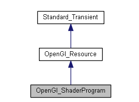
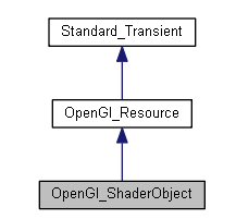
OpenCASCADE从6.7.0之后,Shader程序也成了源码的一部分。程序开发者可以为实现各种特效提供自己的Shader程序。在TKOpenGl库中就有Shader相关的类,如下图所示:

wps_clip_image-16881wps_clip_image-26090

OpenCASCADE中的Shader管理是完全自动完成的,和其他OpenGL的资源一样。仔细看看这几个类相关的函数,会发现与Qt中的Shader比较类似。对比使用,会加快对OpenGL Shader程序的理解。

在OCCT6.7.0版本中的Shader程序还有一些局限性,如不能使用GLSL1.40版本或更新版本的功能。为了克服这个局限性,OCCT为了实现一些shader的操作定义了一些uniform的变量,这样Shader程序就不依赖于GLSL1.30定义的一些变量了,使程序的兼容性更好。在源文件的Shaders文件夹中的Declarations.glsl中定义了这些变量,摘抄部分如下所示:

// Vertex attributes
#ifdef VERTEX_SHADER
  attribute vec4 occVertex;
  attribute vec3 occNormal;
  attribute vec4 occTexCoord;
  attribute vec4 occVertColor;
#endif

// Matrix state
uniform mat4 occWorldViewMatrix;  //!< World-view  matrix
uniform mat4 occProjectionMatrix; //!< Projection  matrix
uniform mat4 occModelWorldMatrix; //!< Model-world matrix

uniform mat4 occWorldViewMatrixInverse;    
//!< Inverse of the world-view  matrix
uniform mat4 occProjectionMatrixInverse;   //!< Inverse of the projection  matrix
uniform mat4 occModelWorldMatrixInverse;   //!< Inverse of the model-world matrix

uniform mat4 occWorldViewMatrixTranspose;  
//!< Transpose of the world-view  matrix
uniform mat4 occProjectionMatrixTranspose; //!< Transpose of the projection  matrix
uniform mat4 occModelWorldMatrixTranspose; //!< Transpose of the model-world matrix

uniform mat4 occWorldViewMatrixInverseTranspose;  
//!< Transpose of the inverse of the world-view  matrix
uniform mat4 occProjectionMatrixInverseTranspose; //!< Transpose of the inverse of the projection  matrix
uniform mat4 occModelWorldMatrixInverseTranspose; //!< Transpose of the inverse of the model-world matrix

与OpenGL的内置uniform变量对比会发现,主要内容都是类似的:

//
uniform mat4  gl_ModelViewMatrix;
uniform mat4  gl_ProjectionMatrix;
uniform mat4  gl_ModelViewProjectionMatrix;
uniform mat4  gl_TextureMatrix[gl_MaxTextureCoords];

//
// Derived matrix state that provides inverse and transposed versions
// of the matrices above. Poorly conditioned matrices may result
// in unpredictable values in their inverse forms.
//
uniform mat3  gl_NormalMatrix; // transpose of the inverse of the upper
                               
// leftmost 3x3 of gl_ModelViewMatrix

uniform mat4  gl_ModelViewMatrixInverse;
uniform mat4  gl_ProjectionMatrixInverse;
uniform mat4  gl_ModelViewProjectionMatrixInverse;
uniform mat4  gl_TextureMatrixInverse[gl_MaxTextureCoords];

uniform mat4  gl_ModelViewMatrixTranspose;
uniform mat4  gl_ProjectionMatrixTranspose;
uniform mat4  gl_ModelViewProjectionMatrixTranspose;
uniform mat4  gl_TextureMatrixTranspose[gl_MaxTextureCoords]

uniform mat4  gl_ModelViewMatrixInverseTranspose;
uniform mat4  gl_ProjectionMatrixInverseTranspose;
uniform mat4  gl_ModelViewProjectionMatrixInverseTranspose;
uniform mat4  gl_TextureMatrixInverseTranspose[gl_MaxTextureCoords]

看样子OpenCASCADE为了GLSL版本兼容性也是动了些脑筋啊!

2.Test Shader

为了方便在OpenCASCADE中测试自定义的Shader程序,OpenCASCADE在Draw Test Harness中提供了一个vshaderprog命令。如下图所示为在Draw Test Harness中使用命令vshaderprog产生的Gouraud Shading和Phong Shading效果:

wps_clip_image-4915

Figure 2.1 Gouraud Shading(Left) and Phong Shading(right) by OCCT

在Draw Test Harness中使用vshaderprog命令很简单,如下图所示:

wps_clip_image-1384

Figure 2.2 vshaderprog usage

为指定的模型指定顶点着色器和片段着色器即可。

3.Gooch Shader

Gooch着色属于非真实性图像着色,主要用于绘制各种手册、技术图书上的示意图。1998年,Bruce和Amy Gooch、Peter Shirley以及Elaine Cohen对示意图进行了调查并提出了使用喷枪和画笔绘制的彩色示意图特征:

v 表面边界、轮廓边缘及对象表面的不连续处通常是使用黑色曲线绘制;

v 使用一个单独的光源,它会在对象上产生白色的高光;

v 光源通常位于对象的上方,这样在对象的可见区域上,漫反射部分会在[0,1]中变化;

v ……

wps_clip_image-12173

Figure 3.1 Gooch Shader Effect

上图所示为Gooch着色器渲染出来的效果,看上去是不是很有感觉啊!以上图片来自Amy Gooch, Bruce Gooch, Peter Shirley和Elaine Cohen的论文:

A Non-Photorealistic Lighting Model For Automatic Technical Illustration.

Department of Computer Science University of Utah. Utah大学还有著名的Utah Teapot。

在《OpenGL Shading Language》一书中发现了Gooch着色器的相关实现代码,如下所示:

顶点着色器Gooch.vs:

//
// Vertex shader for Gooch shading
//
// Author: Randi Rost
//
// Copyright (c) 2002-2005 3Dlabs Inc. Ltd. 
//
// See 3Dlabs-License.txt for license information
//

uniform vec3  LightPosition;  
// (0.0, 10.0, 4.0) 

varying 
float NdotL;
varying vec3  ReflectVec;
varying vec3  ViewVec;

void main()
{
    LightPosition 
= vec3(0.010.04.0);
    
    vec3 ecPos      
= vec3(gl_ModelViewMatrix * gl_Vertex);
    vec3 tnorm      
= normalize(gl_NormalMatrix * gl_Normal);
    vec3 lightVec   
= normalize(LightPosition - ecPos);
    ReflectVec      
= normalize(reflect(-lightVec, tnorm));
    ViewVec         
= normalize(-ecPos);
    NdotL           
= (dot(lightVec, tnorm) + 1.0* 0.5;
    gl_Position     
= ftransform();
}

片段着色器Gooch.fs:

//
// Fragment shader for Gooch shading
//
// Author: Randi Rost
//
// Copyright (c) 2002-2005 3Dlabs Inc. Ltd. 
//
// See 3Dlabs-License.txt for license information
//

uniform vec3  SurfaceColor; 
// (0.75, 0.75, 0.75)
uniform vec3  WarmColor;    // (0.6, 0.6, 0.0)
uniform vec3  CoolColor;    // (0.0, 0.0, 0.6)
uniform float DiffuseWarm;  // 0.45
uniform float DiffuseCool;  // 0.45

varying 
float NdotL;
varying vec3  ReflectVec;
varying vec3  ViewVec;

void main()
{
    SurfaceColor 
= vec3(0.750.750.75);
    WarmColor 
= vec3(0.60.60.0);
    CoolColor 
= vec3(0.00.00.6);
    DiffuseWarm 
= 0.45;
    DiffuseCool 
= 0.45;
    
    vec3 kcool    
= min(CoolColor + DiffuseCool * SurfaceColor, 1.0);
    vec3 kwarm    
= min(WarmColor + DiffuseWarm * SurfaceColor, 1.0); 
    vec3 kfinal   
= mix(kcool, kwarm, NdotL);

    vec3 nreflect 
= normalize(ReflectVec);
    vec3 nview    
= normalize(ViewVec);

    
float spec    = max(dot(nreflect, nview), 0.0);
    spec          
= pow(spec, 32.0);

    gl_FragColor 
= vec4(min(kfinal + spec, 1.0), 1.0);
}

将它们加载到OpenCASCADE中,显示效果如下图所示:

wps_clip_image-8706

Figure 3.2 A Main Engine in Draw Test Harness

wps_clip_image-24159

Figure 3.3 Use Gooch Shader Program

由上图可知,Shader有一定的作用,但效果不是很理想。还需要学习相关的知识,才能完善。如果在OpenCASCADE中只修改下shader就可以得到各种特效,岂不快哉!

4.Conclusion

综上所述,OpenGL的Shader是个很好玩的东西,所以OpenCASCADE中引入了这个。为了保证GLSL的兼容性,OpenCASCADE也定义了一些变量。

在不改变程序源码的情况下,只换上不同的shader,就可以得到各种炫丽的特效,这些特效主要是利用GPU的资源完成,不占用CPU。看OpenGL最新的规格书中,GLSL已经越来越Fashion了!

5. References

1. Randi J. Rost. OpenGL Shading Language. Addison Wesley. 2006

2. Amy Gooch, Bruce Gooch, Peter Shirley, Elaine Cohen. A Non-Photorealistic Lighting Model For Automatic Technical Illustration. Department of Computer Science University of Utah.

3. San, Shader support in OCCT6.7.0. http://dev.opencascade.org/index.php?q=node/902


PDF version and Gooch Shader OpenGL Shader in OpenCASCADE


eryar 2015-07-22 23:12 发表评论

RvmTranslator 2.1 is released

$
0
0

RvmTranslator 2.1 is released

eryar@163.com

1. 完善基本体的转换

在使用RvmTranslator转换过程中发现少了一些模型,经查是早期版本有些基本体的转换没有实现,像Sloped Cylinder和Pyramid:

wps_clip_image-20595

完善程序,将文本格式和二进制格式中转换Sloped Cylinder和Pyramid部分实现。

wps_clip_image-8431

2. 提高转换STEP格式速度

当模型太多时,转换成STEP格式速度很慢。修改程序,大幅提高转换STEP格式速度。


3. RvmTranslator各版本下载

Version

Download

RvmTranslator1.0

Download

RvmTranslator2.0

Download

RvmTranslator2.1

Download


eryar 2015-08-18 22:10 发表评论
Viewing all 208 articles
Browse latest View live


<script src="https://jsc.adskeeper.com/r/s/rssing.com.1596347.js" async> </script>